Your Browsing History
- Free 30-day Returns
$218.69
Ships from Hong Kong.
Sold by LiAnMengYuShangDian
Shipped by LiAnMengYuShangDian

Meet Your Seller
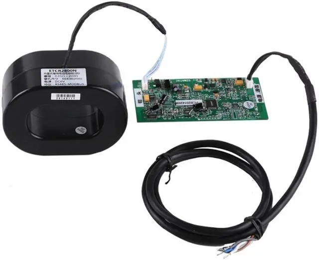


ETCR2800N Built-in Grounding Resistance Online Tester Network System
- ETCR2800N Built-in Grounding Resistance Online Tester Network System
+
+
Overview
Specs
Reviews
Any questions? Our AI mode will help you find out quickly.
Try me now
ETCR2800N Built-in Grounding Resistance Online Tester
Product Main Function
1. On - line monitoring the earth resistance of grounding system
2. Measure Range: 0.010O~200O
3. Equip with RS485( support MODBUS-RTU communication protocol) or GPRS interface
4. can be built into inside case of other equipment ,convenient the secondary development and integration by users
5. Network system can be built to realize real-time detection and remote monitoring
ETCR2800 Non-contact Earth Resistance On-line Monitor is high-tech product that our company has devoted to "grounding resistance detection technology research" for more than ten years, specialize for online monitoring grounding down lead connection status, circuit grounding resistance and metal circuit connection resistance range: 0.010O~200O. On-line testing, non-contact measurement, grounding wire pass through the perforation of the detector, definitely will not influence grounding effective for lightening and normal operation, no need the self-inspection, real time on-line testing. Provide RS485 wire communication (support MODBUS-RTU communication protocol) or GPRS wireless communication data transmission, The monitor is composed of sensor and PCB module, which is suitable for user secondary development integration.
ETCR2800 Non-contact Earth Resistance On-line Monitor can install and use singly, and also can set up wired or wireless network system
Function Loop circuit grounding resistance on-line monitoring, metal return circuit resistance connection online monitoring, grounding condition monitoring. anti-theft monitoring of grounding wires and metal cables
Power Supply Detector:6VDC~9VDC,50mA Max(external power supply).
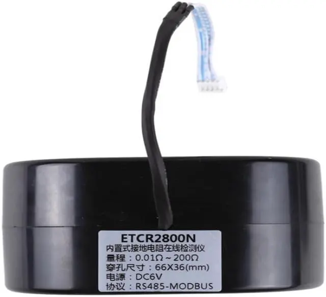
Resistance Range 0.01O~200O
Resolution 0.001O
Accuracy ±2%rdg±3dgt(20?±5?,below 70%RH)
PCB Size 122mm×56mm×20mm
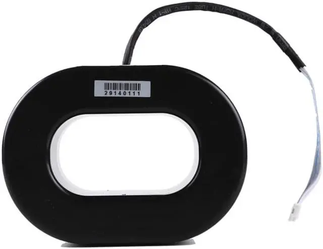
Sensor Size ETCR2800N:110mm×80mm×55mm
Sensor Perforation Size ETCR2800N:65mm×36mm
Sensor Weight ETCR2800N:680g;
Overflow Indication Test data>200O, communication send “OLO” command
PCB Interface J1:Signal output, power input interface
J2:Sensor and PCB interface
Symbol J1 P+:Power input with positive R+:Signal output with positive
P-:Power input ground R-: Signal output with negative
GND:Signal ground, short connect with power input ground (P-)
Symbol J2 I+?I-Current coil interface U+?U-Voltage coil interface
GND:Common ground
Connect Wire 1pcs ,1 meter length(5 core wire)
Connection Identifier Red/brown---power supply input anode;
Black--- power supply input cathode;
Blue---RS485 signal anode;
Grey---RS485 signal cathode;
White--- grounding wire shield
(power supply input cathode can connects with analog grounding by short circuit connection)
Communication method RS485 communication protocol(support MODBUS)
GPRS communication (optional)
Working Temperature And Humidity -20?~55?; 20%RH~90%RH
Shift Automatic shift
Grounding lead Interference Current Should be avoid
External Magnetic Field <40A/m
External Electric Field <1V/m
Single Measurement time About 0.5 second
Working current 50mA Max.
Installation The ground wire goes through the center hole of the sensor
Installation Demand PCB should install into other protective case
Battery does not include
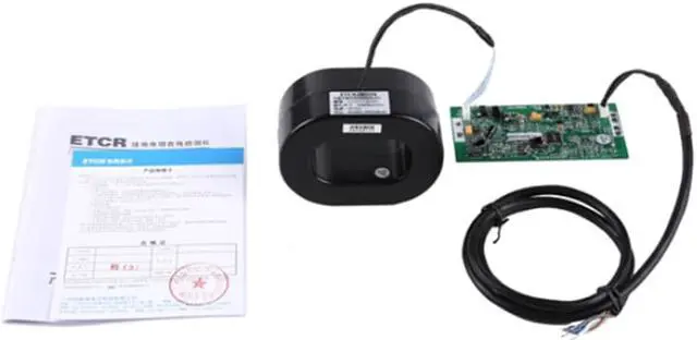
Package Outer package Carton
Inner package None
Accessory Meter 1 pcs
Power and Communication Cable 1 pcs
PCB module 1 pcs
Certificate 1 pcs
Manual 1pcs
Warranty Card 1 pcs
Product Main Function
1. On - line monitoring the earth resistance of grounding system
2. Measure Range: 0.010O~200O
3. Equip with RS485( support MODBUS-RTU communication protocol) or GPRS interface
4. can be built into inside case of other equipment ,convenient the secondary development and integration by users
5. Network system can be built to realize real-time detection and remote monitoring
ETCR2800 Non-contact Earth Resistance On-line Monitor is high-tech product that our company has devoted to "grounding resistance detection technology research" for more than ten years, specialize for online monitoring grounding down lead connection status, circuit grounding resistance and metal circuit connection resistance range: 0.010O~200O. On-line testing, non-contact measurement, grounding wire pass through the perforation of the detector, definitely will not influence grounding effective for lightening and normal operation, no need the self-inspection, real time on-line testing. Provide RS485 wire communication (support MODBUS-RTU communication protocol) or GPRS wireless communication data transmission, The monitor is composed of sensor and PCB module, which is suitable for user secondary development integration.
ETCR2800 Non-contact Earth Resistance On-line Monitor can install and use singly, and also can set up wired or wireless network system
Function Loop circuit grounding resistance on-line monitoring, metal return circuit resistance connection online monitoring, grounding condition monitoring. anti-theft monitoring of grounding wires and metal cables
Power Supply Detector:6VDC~9VDC,50mA Max(external power supply).
Resistance Range 0.01O~200O
Resolution 0.001O
Accuracy ±2%rdg±3dgt(20?±5?,below 70%RH)
PCB Size 122mm×56mm×20mm
Sensor Size ETCR2800N:110mm×80mm×55mm
Sensor Perforation Size ETCR2800N:65mm×36mm
Sensor Weight ETCR2800N:680g;
Overflow Indication Test data>200O, communication send “OLO” command
PCB Interface J1:Signal output, power input interface
J2:Sensor and PCB interface
Symbol J1 P+:Power input with positive R+:Signal output with positive
P-:Power input ground R-: Signal output with negative
GND:Signal ground, short connect with power input ground (P-)
Symbol J2 I+?I-Current coil interface U+?U-Voltage coil interface
GND:Common ground
Connect Wire 1pcs ,1 meter length(5 core wire)
Connection Identifier Red/brown---power supply input anode;
Black--- power supply input cathode;
Blue---RS485 signal anode;
Grey---RS485 signal cathode;
White--- grounding wire shield
(power supply input cathode can connects with analog grounding by short circuit connection)
Communication method RS485 communication protocol(support MODBUS)
GPRS communication (optional)
Working Temperature And Humidity -20?~55?; 20%RH~90%RH
Shift Automatic shift
Grounding lead Interference Current Should be avoid
External Magnetic Field <40A/m
External Electric Field <1V/m
Single Measurement time About 0.5 second
Working current 50mA Max.
Installation The ground wire goes through the center hole of the sensor
Installation Demand PCB should install into other protective case
Battery does not include
Package Outer package Carton
Inner package None
Accessory Meter 1 pcs
Power and Communication Cable 1 pcs
PCB module 1 pcs
Certificate 1 pcs
Manual 1pcs
Warranty Card 1 pcs
Warranty & Returns
Warranty, Returns, And Additional Information
Warranty
- Please contact the Seller directly for warranty information. Warranty information may also be found on the Manufacturer's website.
- CONTACT
Return Policies
- Return for refund within: 30 days
- Return for replacement within: non-replaceable
- This item is covered by LiAnMengYuShangDian Return Policy
Manufacturer Contact Info
- For a directory of all our manufacturers, please click below.
- Manufacturers Directory
LOADING...