Your Browsing History
- Free 30-day Returns
$69.99
Ships from China.

Meet Your Seller


Wireless Desktop Power Button for PC (Laptop Incompatible) , Cool Lights Micro Nuclear Reactor Theme Switch - Silver
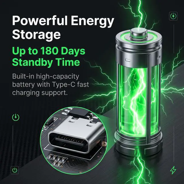
- Wireless switch: uses rechargeable battery, battery life is about 180 days, solar charging, Type-C charging
- One pull to turn on and off: one pull to turn on when in off state, one pull to turn off when on state
- Easy to install, no driver required, does not support all-in-one computers and laptops
+
+
Overview
Specs
Reviews
Any questions? Our AI beta will help you find out quickly.
Try me now
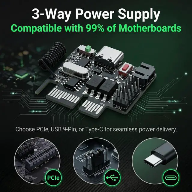
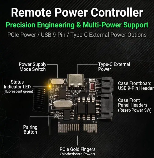
Installation method 1: PCIE power supply
1. The POWER SW jumper is inserted into the boot card terminal.
2. The receiving card can be inserted into the PCI-E card slot of the motherboard or the PCIE interface of the graphics card.
3.Plug the POWER SW female connector into the motherboard POWER SW switch pin
4. The POWER SW male connector is plugged into the original chassis button jumper.
5. Turn the small switch on the boot card to the left to provide PCIE power supply.
Installation method 2: USB nine-pin power supply
1.Plug the POWER SW jumper and USB 9-pin into the boot card terminal.
2. The USB female connector of the receiving card cable is plugged into the motherboard USB interface.
3.Plug the POWER SW female connector into the motherboard POWER SW switch pin
4. The POWER SW male connector is plugged into the original chassis button jumper.
5. Turn the small switch on the boot card to the right to supply power to the USB 9-pin
Note: The above two power supply methods need to be set to power after the motherboard is shut down.
USB 9-pin power supply requires additional USB wake-up
Installation method 3: TYPE-C external power supply
1.Plug the POWER SW line into the boot card terminal
2. Plug TYPE-C into the receiving card, and plug the other end into the mobile phone 5V charger or USB interface (Note: The charging head of the fast charging protocol cannot be used. The output of the charging head should not exceed 5V)
3. POWERSW female connector is inserted into the motherboard POWER SW switch pin.
4. The POWER SW male connector is plugged into the original chassis button jumper.
5. Turn the small switch on the power-on card to the right to power TYPE-C
Warranty & Returns
Warranty, Returns, And Additional Information
Warranty
- Please contact the Seller directly for warranty information. Warranty information may also be found on the Manufacturer's website.
- CONTACT
Return Policies
- Return for refund within: 30 days
- Return for replacement within: 30 days
- This item is covered by B-IN Electronics Return Policy
Manufacturer Contact Info
- For a directory of all our manufacturers, please click below.
- Manufacturers Directory
LOADING...