




 here!
I’m your shopping assistant for PC builds, upgrades, and everything tech.
Got questions? Ask away!
Start a conversation
here!
I’m your shopping assistant for PC builds, upgrades, and everything tech.
Got questions? Ask away!
Start a conversation




Any questions? Ask CelesteSM will help you find out quickly.


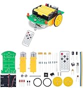
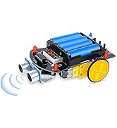
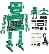
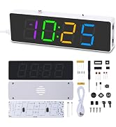
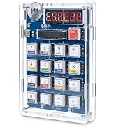
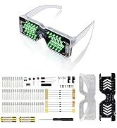
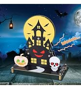
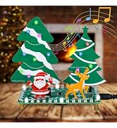
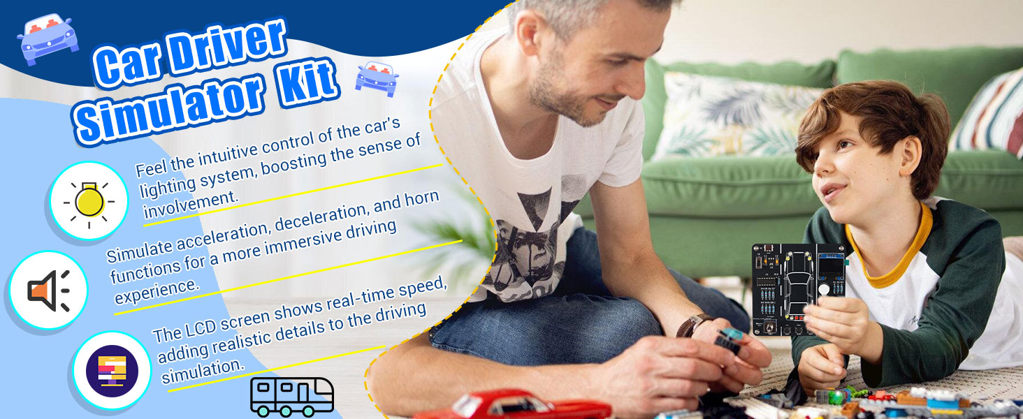
At MIOYOOW, we offer DIY kits for different skill levels, from beginner projects to advanced builds. Our range includes digital clocks, Bluetooth speakers, smart cars, FM radios, LED lights and STEM learning kits, combining learning with hands-on fun.
Each kit is designed to deliver a practical soldering experience, clear instructions are included, and support is available if needed. DIY can be challenging—but that's part of the fun.
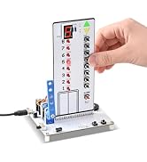
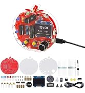

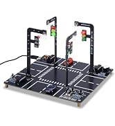


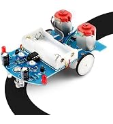



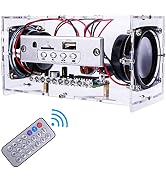
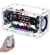
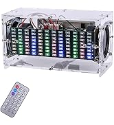
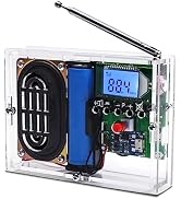




Friendly Reminder: If your display comes with header pins, please skip Step 11 in the manual and solder the display directly.
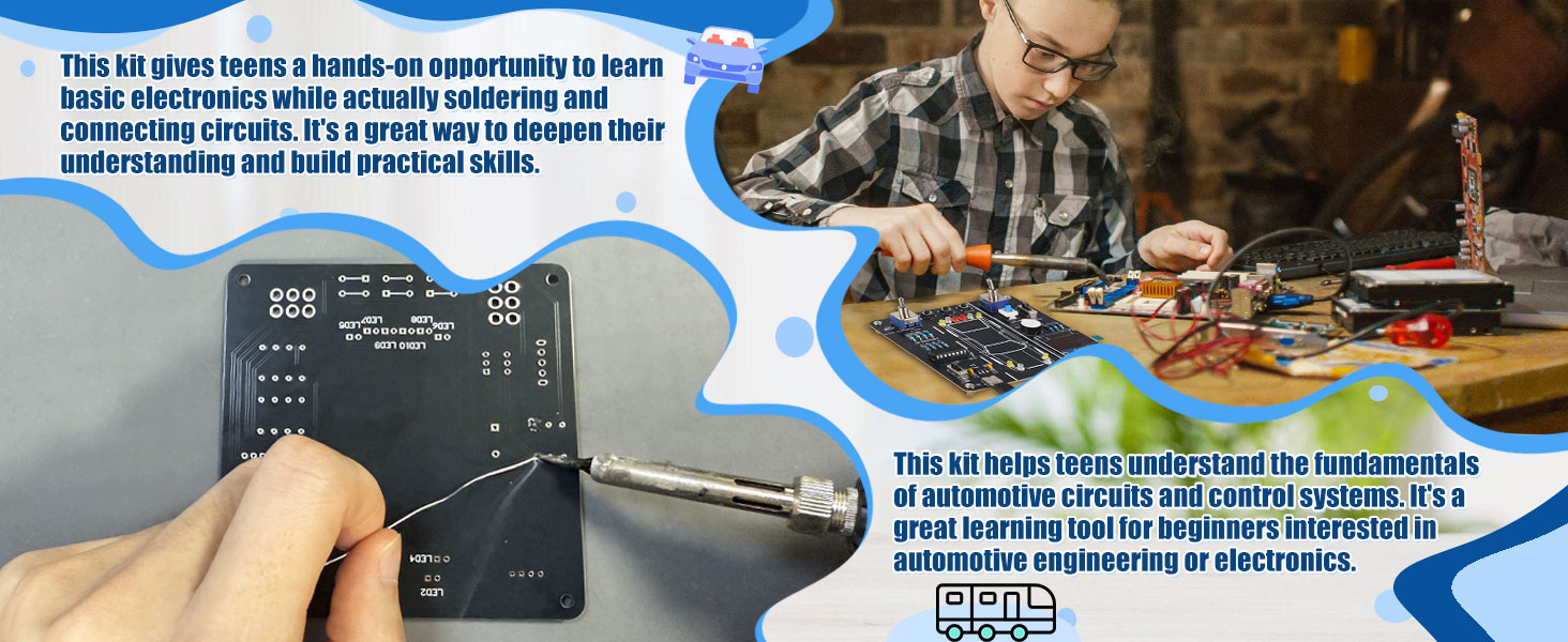
1?Switch Control Principle
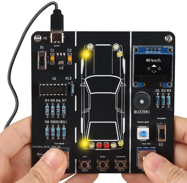
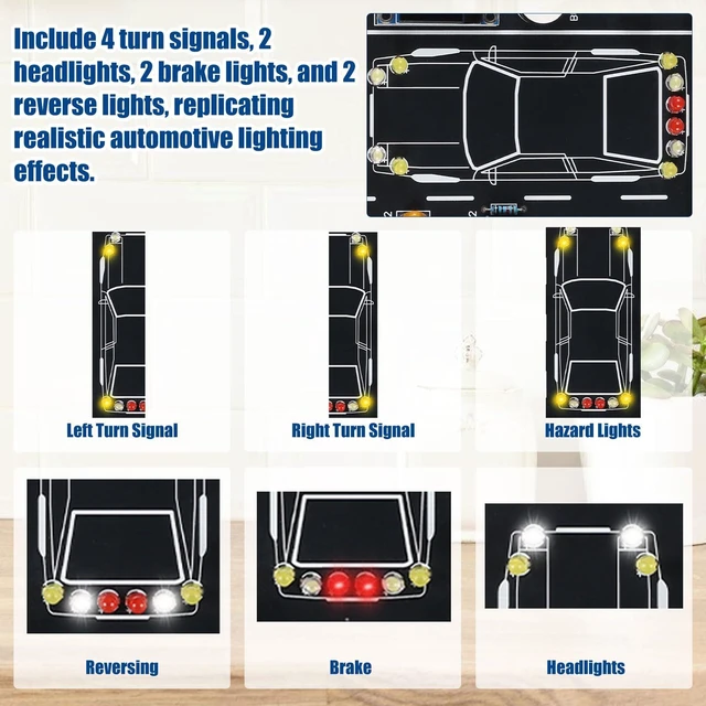
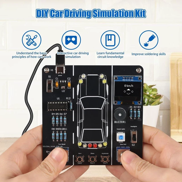
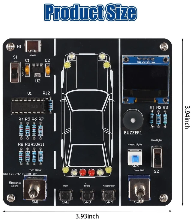
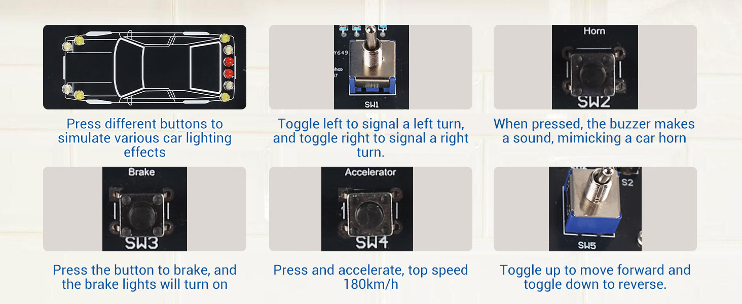
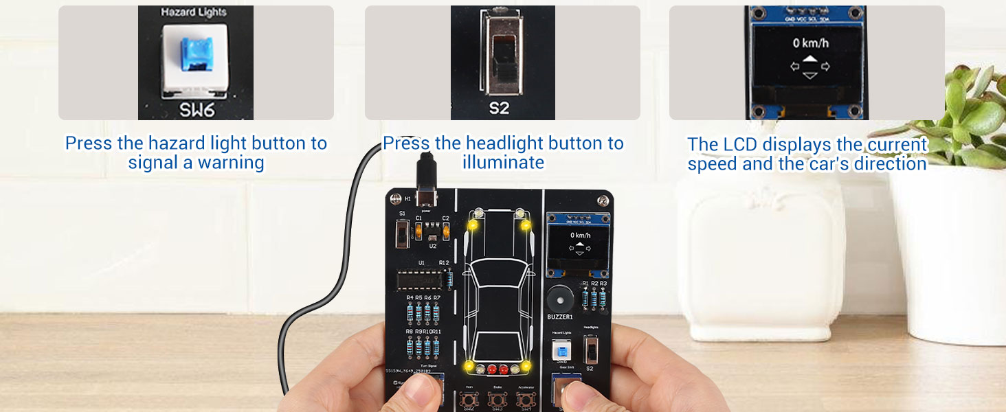
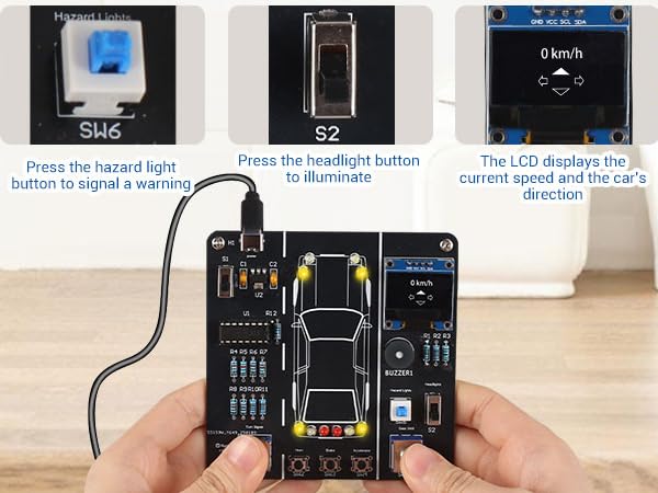
Different car lights (left turn, right turn, high beam, low beam, etc.) are controlled by toggle switches. Principle: When the switch is closed, current flows to the corresponding LED and turns it on; when opened, the LED turns off.
2?LED Illumination and Current Limiting Principle
The car lights are simulated with LEDs, where different colors represent headlights, taillights, and turn signals. Principle: A current-limiting resistor is connected in series with each LED to prevent damage.
3?Parallel Circuit Principle
The car light circuits are connected in parallel, so each group of lights can be controlled independently without affecting the others.
4?LED Flashing Principle
Pulse signals generated by the microcontroller drive the LEDs, enabling automatic flashing effects.
 Physics Experiment Kit |  Traffic Light DIY Kit | 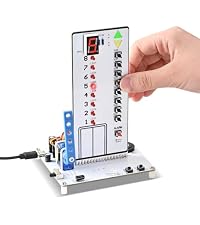 Smart Elevator Kit | 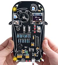 DIY Car Simulation Kit | 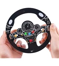 DIY Steering Wheel Kit | 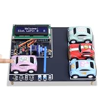 Mini Parking Lot DIY Kit | 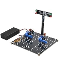 Toll Gate Simulator Kit | |
|---|---|---|---|---|---|---|---|
Customer Reviews | — | — | — | — | — | — | — |
Price | — | — | — | — | — | — | — |
Finished Project | Ohm's Law Circuit Learning | Simulation Traffic Signal | UP/Down Mini Smart Elevator | Car Driving Simulation Model | Steering Wheel Simulation | Parking Lot Simulation | Highway Toll Booth Simulation |
Feature | Learn Series&Parallel Circuits | with Sound and Street Lamp | Voice Floor Announcement | Car Operation Effects | Simulate Car Steering & Sound | with Sound | with Sound |
Working Voltage | DC 5V | DC 3.7-5V | DC 5V | DC 5-7.4V | DC 5V | DC 5V-7.4V(Battery Powered) | DC 5V(Battery Powered) |
Asembled Size | 5.5“ x 1.18” x 4.13" | 5.9" x 5.9" x 4.09" | 4.13" x 3.54" x 5.9" | 6.3" x 3.35" | 5.75" x 5.75" x 0.47" | 6.69“ x 5.11” x 1.65“ | 6.49" x 6.1" x 5.59" |
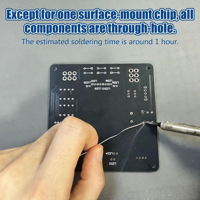
Soldering Type | Through-hole | Through-hole | Through-hole | Through-hole | Through-hole | Through-hole | Through-hole |
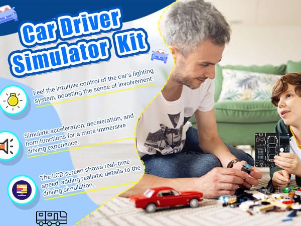
Friendly Reminder: If your display comes with header pins, please skip Step 11 in the manual and solder the display directly.
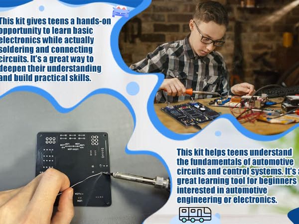
1?Switch Control Principle
Different car lights (left turn, right turn, high beam, low beam, etc.) are controlled by toggle switches. Principle: When the switch is closed, current flows to the corresponding LED and turns it on; when opened, the LED turns off.
2?LED Illumination and Current Limiting Principle
The car lights are simulated with LEDs, where different colors represent headlights, taillights, and turn signals. Principle: A current-limiting resistor is connected in series with each LED to prevent damage.
3?Parallel Circuit Principle
The car light circuits are connected in parallel, so each group of lights can be controlled independently without affecting the others.
4?LED Flashing Principle
Pulse signals generated by the microcontroller drive the LEDs, enabling automatic flashing effects.
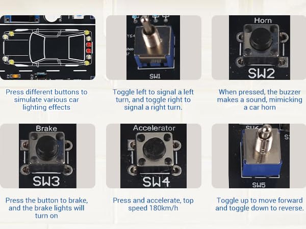
Physics Experiment Kit | Traffic Light DIY Kit | Smart Elevator Kit | DIY Car Simulation Kit | DIY Steering Wheel Kit | Mini Parking Lot DIY Kit | Toll Gate Simulator Kit |
|---|---|---|---|---|---|---|
| Customer Reviews | ||||||
| — | — | — | — | — | — | — |
| Price | ||||||
| — | — | — | — | — | — | — |
| Finished Project | ||||||
| Ohm's Law Circuit Learning | Simulation Traffic Signal | UP/Down Mini Smart Elevator | Car Driving Simulation Model | Steering Wheel Simulation | Parking Lot Simulation | Highway Toll Booth Simulation |
| Feature | ||||||
| Learn Series&Parallel Circuits | with Sound and Street Lamp | Voice Floor Announcement | Car Operation Effects | Simulate Car Steering & Sound | with Sound | with Sound |
| Working Voltage | ||||||
| DC 5V | DC 3.7-5V | DC 5V | DC 5-7.4V | DC 5V | DC 5V-7.4V(Battery Powered) | DC 5V(Battery Powered) |
| Asembled Size | ||||||
| 5.5“ x 1.18” x 4.13" | 5.9" x 5.9" x 4.09" | 4.13" x 3.54" x 5.9" | 6.3" x 3.35" | 5.75" x 5.75" x 0.47" | 6.69“ x 5.11” x 1.65“ | 6.49" x 6.1" x 5.59" |
| Soldering Type | ||||||
| Through-hole | Through-hole | Through-hole | Through-hole | Through-hole | Through-hole | Through-hole |
At MIOYOOW, we offer DIY kits for different skill levels, from beginner projects to advanced builds. Our range includes digital clocks, Bluetooth speakers, smart cars, FM radios, LED lights and STEM learning kits, combining learning with hands-on fun.
Each kit is designed to deliver a practical soldering experience, clear instructions are included, and support is available if needed. DIY can be challenging—but that's part of the fun.


