




 here!
here!
I’m your shopping assistant for PC builds, upgrades, and everything tech.
Got questions? Ask away!
Start a conversation
here!
I’m your shopping assistant for PC builds, upgrades, and everything tech.
Got questions? Ask away!
Start a conversation




Any questions? Ask CelesteSM will help you find out quickly.



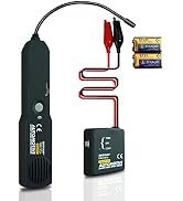
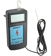
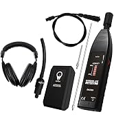
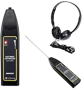

Based on ISO9001 International Quality System, most products are exported to Europe and USA with approvals of CE, UL, GS, CMC.
We have wide product range to meet different purchased requirements. The main products contain Digital Multimeters, Metal Detectors, Ultrasonic Measures, Infrared testers.One-stop style make purchase easy,and greatly reduce purchase cost,shorten purchase time and assure purchase quality control.
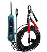




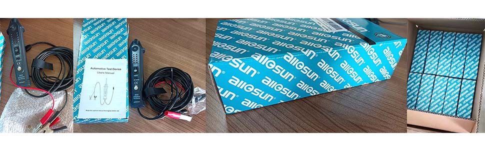
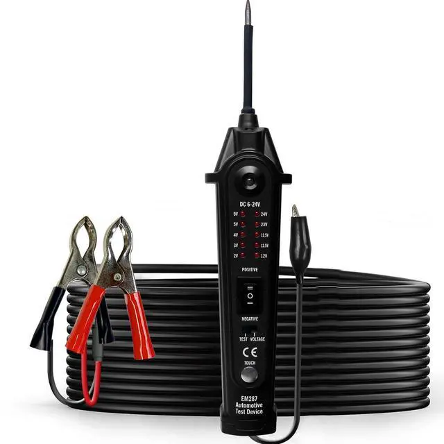
*1pc x allsun Circuit Test Device
*1pc x English User's Manual
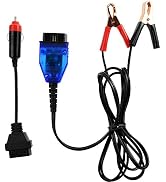
*1pc x Flexi Extension Cable
*1pc x Crocodile Clip(one is Red, the other is Black)
*1pc x Wire Test
*1pc x Back-Test
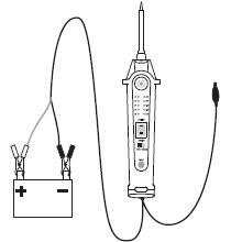
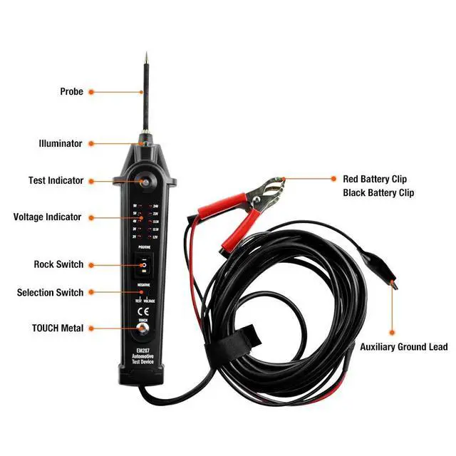
Press the front part(“-’’)of the rock switch,the test indicator should light RED.
Press the rear part (“=’’),the test indicator should light GREEN.
The unit is now ready for use.
If the test indicator did not light,the cause may be that the clip connections are not good or the unit is damaged.
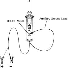
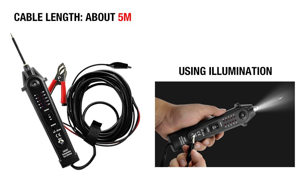
To turn on or off the illuminator,keep the clip of the auxiliary ground lead in contact with the TOUCH metal for about 0.5 second and then remove the clip from the TOUCH metal.
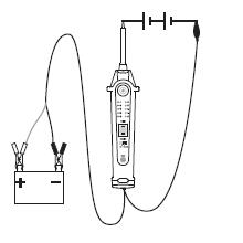
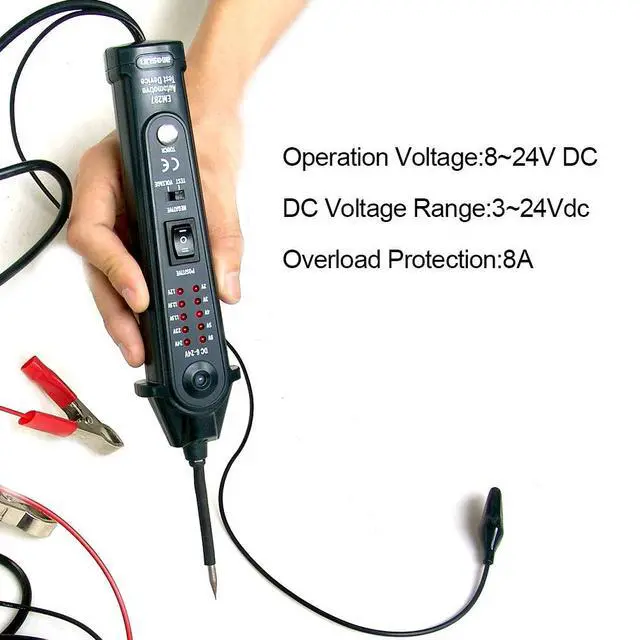
a.Set the selection switch to “VOLTAGE” position.
b.Connect the probe to the more positive terminal of the circuit to be measured,and the clip of the auxiliary ground lead to the more negative terminal of the circuit.
c.The voltage indicators will illuminate to indicate the voltage of the circuit.
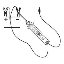
Note:Set the selection switch to “TEST”position.
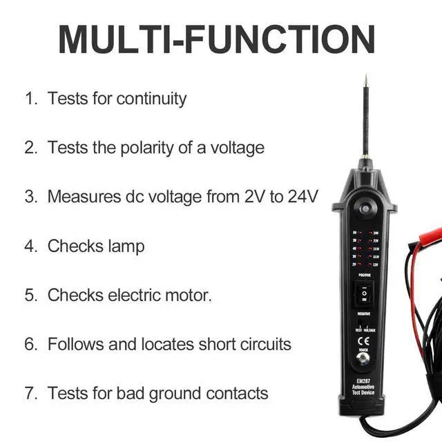
Contacting the probe’s tip to a positive(+) circuit will light the test indicator RED.Contacting the probe’s tip to a negative(-)circuit will light the test indicator GREEN.Contacting the probe’s tip to an open circuit does not turn on the test indicator.
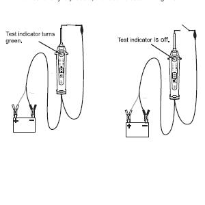
Note:1.Set the selection switch to “TEST”position.
2. Don’t press the rock switch,
By using the probe tip together with the auxiliary ground lead, continuity can be tested on wires and components which are disconnected from the vehicle’s electrical system.
When continuity is present, the test indicator will light GREEN.
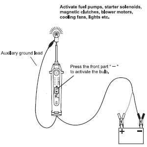
Note:Set the selection switch to”TEST”position.
By using the probe tip together with the auxiliary ground lead,components can be
activated,thereby testing their function.
Connect the auxiliary ground lead’s clip to the negative terminal of the component to be tested.Contact the probe to the positive terminal of the component, the test indicator should light GREEN indicating continuity through the component.
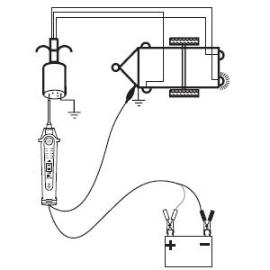
1)Set the selection switch to “TEST”position.
2)Connect the unit to a good battery.
3)Clip the clip of the auxiliary ground lead to the trailer ground.
4)Probe the contacts at the jack while pressing the rock switch’s front par((“-’’).This lets you check the operation and orientation of the trailer lamps.
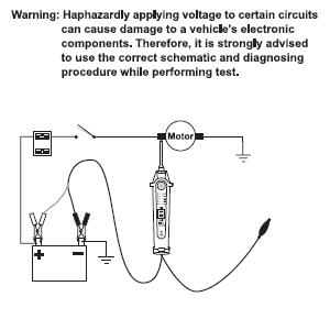
Note:Set the selection switch to”TEST”position.
a.Activating components with the positive(+)voltage,Contact the probe tip to the positive terminal of the component,the test indicator should light GREEN.While keeping an eye on the green indicator,quickly press and release the rock switch’s front part(“-’’).If the green indicator changed instantly from GREEN to RED,you may proceed with further activation.If the green indicator went off at that instant,the uit has been overloaded.
b.Activating electrical components with negative(-)voltage
Contact the probe tip to the negative terminal of the component,the test indicator should light RED.
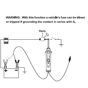
Note:Set the selection switch to”TEST” position.
The black battery clip and the auxiliary ground lead are connected directly through the unit.By leaving the red battery clip disconnected from the vehicle’s battery,the unit can be used as a long jumper lead.
Be careful to avoid short circuit and overloading when using this jumper function.In this configuration, the leads are not protected by the unit’s built-in circuit breaker.
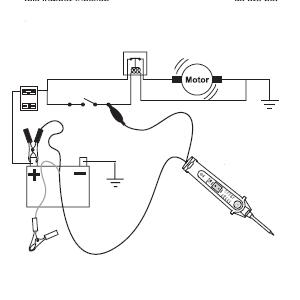
Note:Set the selection switch to”TEST”position.
Probe the suspected ground wire or contact with the probe tip.Observe the green test indicator.
Press the rock switch’s front part(“-”)then release.
If the test indicator changed from GREEN to RED,this is not a true ground.
If the test indicator turned off when you pressed the rock switch’s front part(“-”)

Based on ISO9001 International Quality System, most products are exported to Europe and USA with approvals of CE, UL, GS, CMC.
We have wide product range to meet different purchased requirements. The main products contain Digital Multimeters, Metal Detectors, Ultrasonic Measures, Infrared testers.One-stop style make purchase easy,and greatly reduce purchase cost,shorten purchase time and assure purchase quality control.
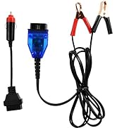
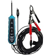
*1pc x allsun Circuit Test Device
*1pc x English User's Manual
*1pc x Flexi Extension Cable
*1pc x Crocodile Clip(one is Red, the other is Black)
*1pc x Wire Test
*1pc x Back-Test
Press the front part(“-’’)of the rock switch,the test indicator should light RED.
Press the rear part (“=’’),the test indicator should light GREEN.
The unit is now ready for use.
If the test indicator did not light,the cause may be that the clip connections are not good or the unit is damaged.
To turn on or off the illuminator,keep the clip of the auxiliary ground lead in contact with the TOUCH metal for about 0.5 second and then remove the clip from the TOUCH metal.
a.Set the selection switch to “VOLTAGE” position.
b.Connect the probe to the more positive terminal of the circuit to be measured,and the clip of the auxiliary ground lead to the more negative terminal of the circuit.
c.The voltage indicators will illuminate to indicate the voltage of the circuit.
Note:Set the selection switch to “TEST”position.
Contacting the probe’s tip to a positive(+) circuit will light the test indicator RED.Contacting the probe’s tip to a negative(-)circuit will light the test indicator GREEN.Contacting the probe’s tip to an open circuit does not turn on the test indicator.
Note:1.Set the selection switch to “TEST”position.
2. Don’t press the rock switch,
By using the probe tip together with the auxiliary ground lead, continuity can be tested on wires and components which are disconnected from the vehicle’s electrical system.
When continuity is present, the test indicator will light GREEN.
Note:Set the selection switch to”TEST”position.
By using the probe tip together with the auxiliary ground lead,components can be
activated,thereby testing their function.
Connect the auxiliary ground lead’s clip to the negative terminal of the component to be tested.Contact the probe to the positive terminal of the component, the test indicator should light GREEN indicating continuity through the component.
1)Set the selection switch to “TEST”position.
2)Connect the unit to a good battery.
3)Clip the clip of the auxiliary ground lead to the trailer ground.
4)Probe the contacts at the jack while pressing the rock switch’s front par((“-’’).This lets you check the operation and orientation of the trailer lamps.
Note:Set the selection switch to”TEST”position.
a.Activating components with the positive(+)voltage,Contact the probe tip to the positive terminal of the component,the test indicator should light GREEN.While keeping an eye on the green indicator,quickly press and release the rock switch’s front part(“-’’).If the green indicator changed instantly from GREEN to RED,you may proceed with further activation.If the green indicator went off at that instant,the uit has been overloaded.
b.Activating electrical components with negative(-)voltage
Contact the probe tip to the negative terminal of the component,the test indicator should light RED.
Note:Set the selection switch to”TEST” position.
The black battery clip and the auxiliary ground lead are connected directly through the unit.By leaving the red battery clip disconnected from the vehicle’s battery,the unit can be used as a long jumper lead.
Be careful to avoid short circuit and overloading when using this jumper function.In this configuration, the leads are not protected by the unit’s built-in circuit breaker.
Note:Set the selection switch to”TEST”position.
Probe the suspected ground wire or contact with the probe tip.Observe the green test indicator.
Press the rock switch’s front part(“-”)then release.
If the test indicator changed from GREEN to RED,this is not a true ground.
If the test indicator turned off when you pressed the rock switch’s front part(“-”)
| Brand | allsun |
| Power Source | Battery Powered,electric |
| Style | Automotive Electrical Circuit Tester |
| Color | Black |
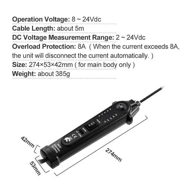
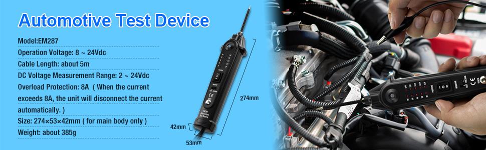
| Item dimensions L x W x H | 10.79 x 2.09 x 1.65 inches |
| Minimum Operating Voltage | 2 volts_of_direct_current |
| Upper Temperature Rating | 125 °C |
| Measurement Type | Voltmeter |
| Style Name | Automotive Electrical Circuit Tester |
| Item Dimensions | 10.79 x 2.09 x 1.65 inches |
| Specification Met | Em287 |
| Brand Name | allsun |
| Model | EM287 |
| UPC | 788537552338 |
| Manufacturer | Zhang Zhou Shi Xiang Cheng Qu Hai Mao Dian Zi Ke Ji co., LTD |
| Part Number | allsunEM287 |


