Your Browsing History
Best Sellers
- $181.99
- + FREE SHIPPING

Meet Your Seller
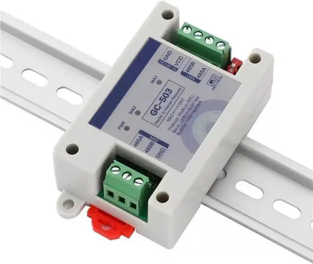
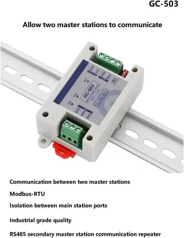
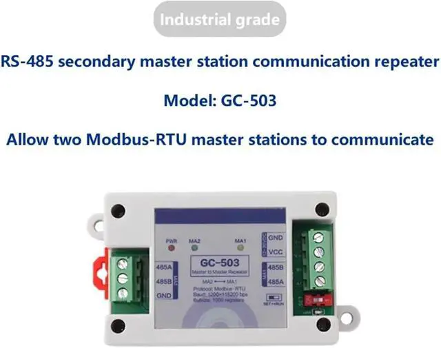


RS485 2 Master Station Communication Repeater, Inter-Master Station Communication Modbus Protocol Data Sharer
- Thermostats & Accessories
- RS485 2 Master Station Communication Repeater, Inter-Master Station Communication Modbus Protocol Data Sharer
+
+
Overview
Specs
Reviews
Any questions? Our AI beta will help you find out quickly.
Try me now
Thermostats & Accessories
Module parameters
Model: GC-503 (RS485 two-master communication repeater)
Working voltage: DC9~30V
Working current: 100mA
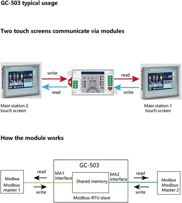
Function overview: realize data interaction between two Modbus master stations
Applicable protocol: Modbus-RTU
Cache size: 500 register data can be cached*2
Interface: 2 RS485 interfaces (both connected to the master station)
Indicator lights: 3 indicator lights (one power light + two communication indicator lights)
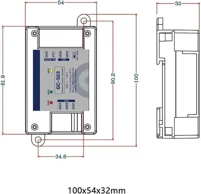
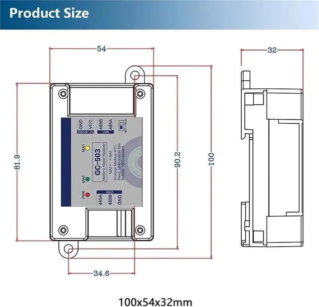
Product size: length, width and height 100x54x32mm (including both ends)
Product weight: 80g (net weight) 100g (gross weight, including accessories and box)
Operating environment: -40~85, relative humidity 5%-95%
Communication parameters
Communication type: Isolated RS-485 (isolation voltage 2500V)
Communication protocol: Modbus RTU (master + slave)
Communication distance: 1200 meters
Baud rate: 1200 -115200bps, default 9600 (8,n,1)
Others: Stop bit can be set, check bit can be set
Protection level: RS-485 interface 600W surge protection per line, ±15KV ESD protection
Interface definition
Main station 2 end
Terminal/Mark/Definition
The 1/485A/MA2 port needs to be connected to the master station, and GND generally does not need to be connected.
The 2/485B/MA2 port needs to be connected to the master station, and GND generally does not need to be connected.
3/GND/MA2 port needs to be connected to the master station, GND generally does not need to be connected
Main station 1 end
Terminal/Mark/Definition
1/GND/power 0V
2/VCC/Power supply 12~30V
3/485B/MA1 interface needs to be connected to the master station
The 4/485A/MA1 interface needs to be connected to the master station
Turn the DIP switch /ON/ to ON, and the module enters configuration mode.
Turn the DIP switch /OFF/ to OFF and the module starts running.
Indicator light description
PWR: power indicator light. Always on means the module is powered
MA1, MA2 interface indicator lights. Flashing indicates that the MA1 and MA2 interfaces are communicating.
==========
Supply Voltage : DC9~30V
Type : Voltage Regulator
Condition :
Module parameters
Model: GC-503 (RS485 two-master communication repeater)
Working voltage: DC9~30V
Working current: 100mA
Function overview: realize data interaction between two Modbus master stations
Applicable protocol: Modbus-RTU
Cache size: 500 register data can be cached*2
Interface: 2 RS485 interfaces (both connected to the master station)
Indicator lights: 3 indicator lights (one power light + two communication indicator lights)
Product size: length, width and height 100x54x32mm (including both ends)
Product weight: 80g (net weight) 100g (gross weight, including accessories and box)
Operating environment: -40~85, relative humidity 5%-95%
Communication parameters
Communication type: Isolated RS-485 (isolation voltage 2500V)
Communication protocol: Modbus RTU (master + slave)
Communication distance: 1200 meters
Baud rate: 1200 -115200bps, default 9600 (8,n,1)
Others: Stop bit can be set, check bit can be set
Protection level: RS-485 interface 600W surge protection per line, ±15KV ESD protection
Interface definition
Main station 2 end
Terminal/Mark/Definition
The 1/485A/MA2 port needs to be connected to the master station, and GND generally does not need to be connected.
The 2/485B/MA2 port needs to be connected to the master station, and GND generally does not need to be connected.
3/GND/MA2 port needs to be connected to the master station, GND generally does not need to be connected
Main station 1 end
Terminal/Mark/Definition
1/GND/power 0V
2/VCC/Power supply 12~30V
3/485B/MA1 interface needs to be connected to the master station
The 4/485A/MA1 interface needs to be connected to the master station
Turn the DIP switch /ON/ to ON, and the module enters configuration mode.
Turn the DIP switch /OFF/ to OFF and the module starts running.
Indicator light description
PWR: power indicator light. Always on means the module is powered
MA1, MA2 interface indicator lights. Flashing indicates that the MA1 and MA2 interfaces are communicating.
==========
Supply Voltage : DC9~30V
Type : Voltage Regulator
Condition :
Warranty & Returns
Warranty, Returns, And Additional Information
Warranty
- Please contact the Seller directly for warranty information. Warranty information may also be found on the Manufacturer's website.
- CONTACT
Return Policies
- Return for refund within: 30 days
- Return for replacement within: non-replaceable
- This item is covered by Coretix Return Policy
Manufacturer Contact Info
- For a directory of all our manufacturers, please click below.
- Manufacturers Directory
LOADING...
LOADING...