Your Browsing History
- Free 30-day Returns
$7.99

Meet Your Seller
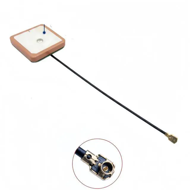


28dB High Gain GPS Active Antenna Built-in Ceramic Patch GPS Antenna U.FL Connector, GPS Module Receiver, for Timing, Marine Navigation, Drone, UAV, Vehicle Tracking, for NEO-6M/7M/8M (25x25x4mm)
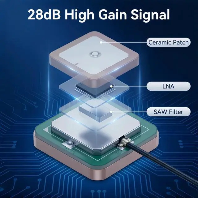
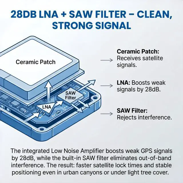
- 28DB HIGH GAIN ACTIVE GPS ANTENNA SUPERIOR SIGNAL RECEPTION Built with a high-performance 28dB integrated Low Noise Amplifier (LNA) and ceramic patch technology, this active GPS antenna delivers exceptional signal reception even in challenging environments. The built-in SAW filter effectively filters out out-of-band interference, ensuring clean and stable GPS signal output. Whether youre in an urban canyon or under light tree cover, this antenna picks up weak satellite signals that passive antennas miss.
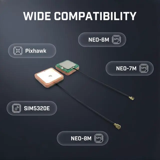
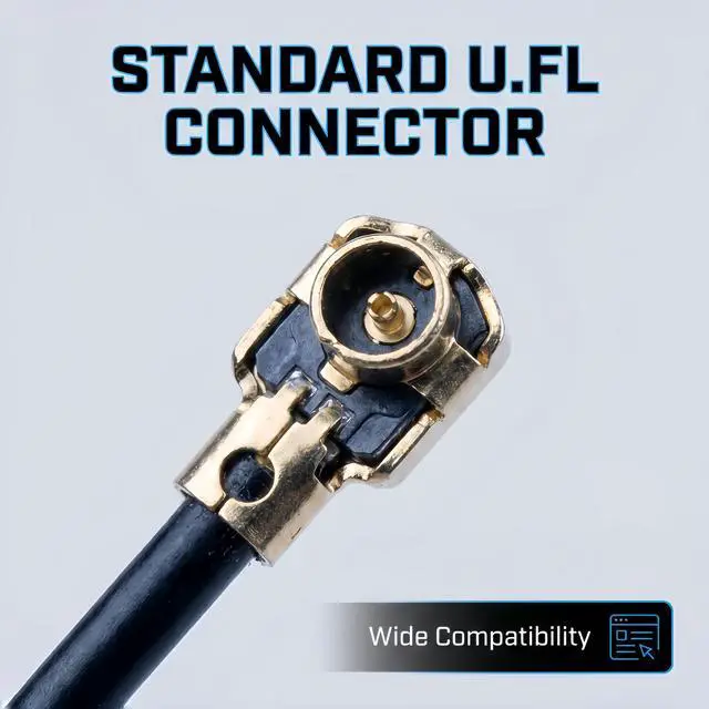
- U.FL (IPEX) CONNECTOR PLUG-AND-PLAY COMPATIBILITY Equipped with a standard U.FL (IPEX / MHF1) female connector, this antenna snaps directly onto the antenna port of most modern SMD GPS modules and cellular boards. No soldering required simply press the connector straight down onto the boards matching U.FL male port until it clicks. Compatible with popular GPS modules including NEO-6M, NEO-7M, NEO-8M, SIM5320E, and other L1-band GNSS receivers.
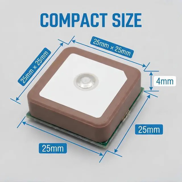
- COMPACT CERAMIC PATCH DESIGN EASY INTEGRATION The 25x25x4mm ultra-compact ceramic patch occupies minimal space while delivering optimal circular polarization for GPS L1 band signals at 1575.42MHz. The low-profile design fits easily into drones, vehicle trackers, IoT devices, and marine navigation systems. The ceramic patch is specifically optimized for the Right Hand Circular Polarization (RHCP) of GPS satellite signals, providing significantly better performance than standard wire antennas.
+
+
Overview
Specs
Reviews
Any questions? Our AI mode will help you find out quickly.
Try me now
About this item
Technical Specifications
- 28DB HIGH GAIN ACTIVE GPS ANTENNA SUPERIOR SIGNAL RECEPTION Built with a high-performance 28dB integrated Low Noise Amplifier (LNA) and ceramic patch technology, this active GPS antenna delivers exceptional signal reception even in challenging environments. The built-in SAW filter effectively filters out out-of-band interference, ensuring clean and stable GPS signal output. Whether youre in an urban canyon or under light tree cover, this antenna picks up weak satellite signals that passive antennas miss.
- U.FL (IPEX) CONNECTOR PLUG-AND-PLAY COMPATIBILITY Equipped with a standard U.FL (IPEX / MHF1) female connector, this antenna snaps directly onto the antenna port of most modern SMD GPS modules and cellular boards. No soldering required simply press the connector straight down onto the boards matching U.FL male port until it clicks. Compatible with popular GPS modules including NEO-6M, NEO-7M, NEO-8M, SIM5320E, and other L1-band GNSS receivers.
- COMPACT CERAMIC PATCH DESIGN EASY INTEGRATION The 25x25x4mm ultra-compact ceramic patch occupies minimal space while delivering optimal circular polarization for GPS L1 band signals at 1575.42MHz. The low-profile design fits easily into drones, vehicle trackers, IoT devices, and marine navigation systems. The ceramic patch is specifically optimized for the Right Hand Circular Polarization (RHCP) of GPS satellite signals, providing significantly better performance than standard wire antennas.
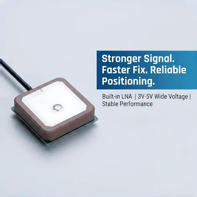
- WIDE VOLTAGE RANGE 3V TO 5V DC OPERATION The active antenna is powered directly through the coaxial signal cable from your GPS module, supporting a wide input voltage range of 3V to 5V DC with typical current consumption of only 10mA. The low power draw makes it ideal for battery-powered applications such as portable trackers, drones, and handheld devices.
- VERSATILE APPLICATIONS TIMING, MARINE, DRONE, VEHICLE TRACKING Engineered for a wide range of professional and hobbyist applications: Timing & Synchronization: Precision timing for network synchronization, financial systems, and scientific equipment Marine Navigation: Reliable GPS signal for boats, cargo ships, sailing vessels, and marine electronics Drone & UAV: Lightweight, high-gain positioning for flight controllers like Pixhawk, APM, and DJI-based systems Vehicle Tracking: Hidden GPS tracking units for cars, bikes, and fleet management systems IoT & Embedded Systems: GPS functionality for cellular modules, portable mapping devices, and outdoor data loggers
- DURABLE CONSTRUCTION WIDE TEMPERATURE RANGE Rated for reliable operation from -40°C to +85°C, this antenna withstands harsh environmental conditions including marine salt spray, desert heat, and freezing temperatures. The ceramic patch is pressure-resistant and built for long-term durability in demanding applications.
Unlock the full potential of your GPS module with this high-performance 28dB Active Ceramic GPS Antenna. Unlike passive antennas that rely solely on the ceramic patch, this active antenna features an integrated Low Noise Amplifier (LNA) and SAW filter that boost weak satellite signals while filtering out interference, delivering faster Time-To-First-Fix (TTFF) and stable positioning even in challenging environments.
Whether youre building a drone, installing a vehicle tracker, setting up marine navigation, or working on precision timing applications, this compact 25x25x4mm antenna provides the sensitivity you need.
Why Choose an Active GPS Antenna?| Signal Amplification | Passive Antenna?(No) With this Active Antenna: 28dB LNA gain for weak signal reception |
| Noise Filtering | Passive Antenna?(No) With this Active Antenna: Built-in SAW filter reduces interference |
| Performance in Urban Areas | Passive Antenna?(Poor (canyon effects)) With this Active Antenna: Excellent picks up weak signals |
| Indoor Reception | Passive Antenna?(Very limited) With this Active Antenna: Works indoors (with clear sky view) |
| Power Requirement | Passive Antenna?(No) With this Active Antenna: 3V-5V via coax cable (10mA typical) |
| Antenna Type | Active Ceramic GPS Patch Antenna |
| Frequency | 1575.42 MHz ± 1 MHz (GPS L1 Band) |
| Integrated LNA Gain | 28 dBi (typical) |
| Ceramic Patch Gain | 3 dBi |
| Noise Figure | < 2dB |
| VSWR | 2.0 |
| Impedance | 50 Ohms |
| Polarization | Right Hand Circular Polarization (RHCP) |
| Operating Voltage | 3V 5V DC (powered via signal cable) |
| Current Consumption | 10mA (typical), <20mA max |
| Connector Type | U.FL (IPEX / MHF1) Female |
| Ceramic Patch Size | 25 x 25 x 4 mm |
| Cable Length | 7.8 inches / 20 cm (typical) |
| Operating Temperature | -40°C to +85°C |
| Storage Temperature | -50°C to +85°C |
This antenna works with any GPS/GNSS receiver module that has a U.FL female antenna port
*Note: For 3.3V-only modules, verify that the module can provide sufficient current (10mA typical) to power the active antenna. Some 3.3V modules may work, but 5V operation is recommended for optimal performance.*
Compatible GPS Modules| NEO-6M / NEO-7M / NEO-8M | Fully compatible |
| SIM5320E / SIM800 series | Compatible (requires active antenna support) |
| Adafruit Ultimate GPS | Compatible (5V operation) |
| Ublox ZED-F9P / NEO-M8N | Compatible |
| Ardupilot Pixhawk flight | Compatible |
| SMD GPS modules with U.FL port | Compatible |
Step 1: Identify Your GPS Modules Antenna Port Locate the U.FL (IPEX) female connector on your GPS module this is a small gold-colored circular port.
Step 2: Connect the Antenna Align the U.FL male connector (on the antenna cable) with the U.FL female port on your GPS module. Press straight down firmly until you hear a soft CLICK. Do not apply sideways pressure or pull at an angle U.FL connectors are rated for a limited number of mating cycles and can be damaged by improper handling.
Step 3: Position the Antenna For optimal performance, the ceramic (light-colored) side of the antenna must face upward toward the open sky. Avoid placing the antenna directly under metal sheets or thick carbon fiber, as these materials block GPS signals. Plastic, glass, and wood are generally transparent to GPS signals.
Step 4: Secure the Antenna Most versions include a 3M adhesive backing for easy mounting inside plastic enclosures, on dashboards, or inside drone frames.
Step 5: Test the Connection Power up your GPS module and allow 30-60 seconds for initial satellite acquisition (Time-To-First-Fix). Once locked, you should see strong signal strength readings from multiple satellites.
1. U.FL Connector Handling U.FL connectors are designed for a limited number of insertion cycles. Use a small tool or fingernail to snap the connector straight down onto the board; avoid applying sideways pressure or frequent disconnecting.
2. Sky View Requirement For optimal performance, the ceramic side of the antenna must face upward toward the open sky. Metal objects, dense foliage, and building structures will degrade signal quality.
3. Power Supply This is an active antenna that requires power (3V-5V DC) via the coaxial cable from your GPS module. Ensure your GPS module is configured to provide power to the antenna port. Some modules have a jumper or software setting to enable antenna power.
4. Signal Blocking Materials Metal and carbon fiber block GPS signals. Do not mount the antenna directly under metal roofs, metal dashboards, or carbon fiber drone frames. Plastic and fiberglass enclosures are generally acceptable.
5. Ground Plane For best performance, mount the antenna on a metal surface (ground plane) or ensure the GPS module has adequate grounding. The ceramic patch antenna is designed to work with an underlying ground plane for optimal gain.
6. Initial Acquisition Time Allow 30-60 seconds for the first satellite lock after power-up, especially in new locations. Subsequent fixes will be faster.
Warranty & Returns
Warranty, Returns, And Additional Information
Warranty
- Please contact the Seller directly for warranty information. Warranty information may also be found on the Manufacturer's website.
- CONTACT
Return Policies
- Return for refund within: 30 days
- Return for replacement within: 30 days
- This item is covered by lilila-reeUS Return Policy
Manufacturer Contact Info
- For a directory of all our manufacturers, please click below.
- Manufacturers Directory
LOADING...