Your Browsing History
- Free 30-day Returns
$19.99
Ships from China.

Meet Your Seller
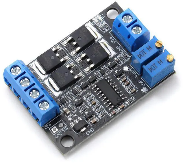
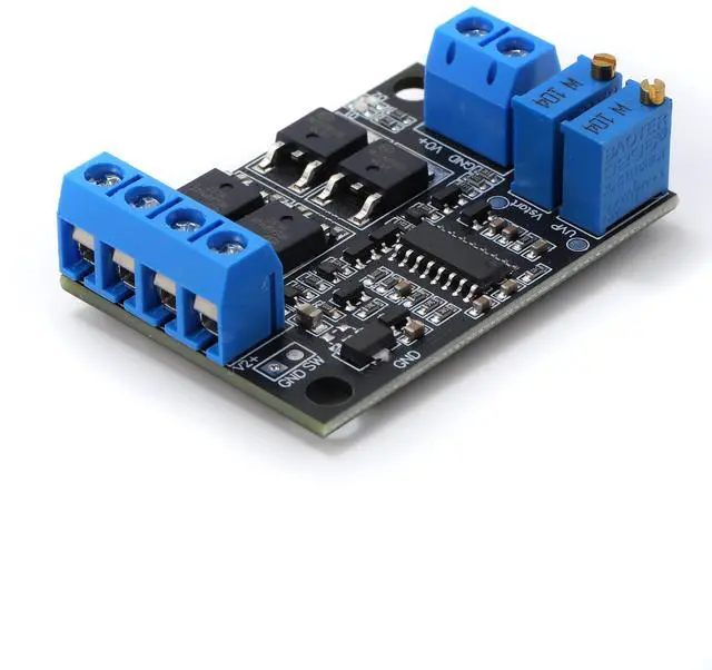
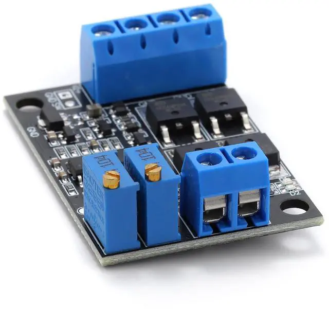
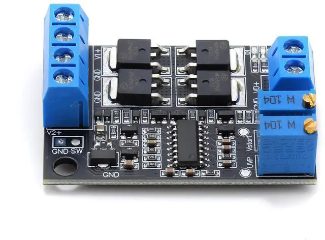


BUCIER Dual DC Power Switching Module Dual Low Voltage Differential Ideal Diode 15A UPS Uninterruptible Power Supply 1pcs
- Operating voltage range: 6~36V.
- Maximum output current: 8A for low power version, 15A for high power version.
- Module self-consumption about 6mA or so
- Adopt ultra-low power consumption 8-bit MCU as the main control, switching quickly and accurately.
- Adopt high power and low loss MOS tube
- 2 power supply indicator lights on board, you can know the power supply status in real time.
- Switching time is about 0.1mS.
- On-board precision multi-turn potentiometer, can freely adjust the main power supply switching voltage and recovery voltage, convenient for a variety of different voltage occasions.
- The main power supply voltage can be higher or lower than the secondary power supply voltage.
- The module does not have charging function, the main power supply can not charge the vice power supply.Wiring mode: lock wire terminal
+
+
Overview
Specs
Reviews
Any questions? Our AI beta will help you find out quickly.
Try me now
Pin Description:1: Mains power input positive 2: Main power input negative (ground) 3: Standby power input negative (ground) 4: Standby power input positive 5: Output negative (ground) 6: Output positive Indicator light: D1: red light, bright when main power V1 is powered, extinguished when secondary power V2 is powered. D2: Green light, on when the secondary power supply V2 is powered, off when the main power supply V1 is powered. Potentiometer: VR1: main power switching voltage adjustment potentiometer. When the main power supply voltage is lower than the voltage set by VR1, the main power supply will be switched off immediately and the output will be switched to the backup power supply. Main power switching voltage VUVP for the test point TP1 voltage 5 times, according to the following formula:VUVP=VTP1×5 (V) For example, if the potentiometer VR1 is adjusted so that the TP1 voltage is 2V, then the switching voltage VUVP = 2 × 5 = 10 (V). When the main power supply V1 voltage is lower than 10V, it immediately cuts off the main power supply and at the same time switches to the standby power supply. The default shipping switching voltage is 10V. VR2: Main power supply recovery voltage VSTART adjustment potentiometer. When the main power supply voltage is higher than the voltage set by VR2, it immediately switches off the standby power supply and returns to the main power supply output. The main power supply recovery voltage VSTART is 5 times the voltage of the test point TP2, calculated according to the following formula:VSTART=VTP2×5 (V) For example, adjust potentiometer VR2 so that the TP2 voltage is 2.2V, then the main power supply recovery voltage VSTART = 2.2 × 5 = 11 (V). When the main power voltage is higher than 11V, switch the main power supply again and cut off the standby power at the same time. The default delivery recovery voltage is 11V. SW: output power switch, can be connected to an external switch to control the output off and on. Open circuit: open the output. Short circuit: close the output. Cautions: 1: It must be ensured that the recovery voltage is higher than the switching voltage, otherwise the switching may not be normal and other unexpected phenomena. 2: After switching to the secondary power supply, the main power supply voltage returns to normal for more than 3 seconds before switching to the main power supply. 3: The test points TP1 and TP2 are located next to the potentiometer, and they are all to ground voltage. The main power supply, sub power supply and output are common ground.
Warranty & Returns
Warranty, Returns, And Additional Information
Warranty
- Please contact the Seller directly for warranty information. Warranty information may also be found on the Manufacturer's website.
- CONTACT
Return Policies
- Return for refund within: 30 days
- Return for replacement within: 30 days
- This item is covered by Electronics store Return Policy
Manufacturer Contact Info
- For a directory of all our manufacturers, please click below.
- Manufacturers Directory
LOADING...