





Casmer Fireplace Control
Casmer: Universal fireplace remotes for effortless control. Smart,compatible,and user-friendly—bringing convenience and warmth to home
Revolutionize Your Fireplace Experience!
From Flickering Flames to Intense Heat, Our Universal Remote Brings Effortless Control and Endless Comfort.
It's Compatible with more than the Leading Brands.
With Just One Device, You Get a Myriad of Compatible Brands and Comfort Right at Your Fingertips, Unlocking Unlimited Comfort Possibilities.
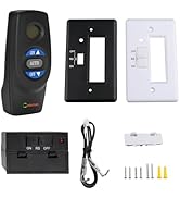
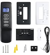

Casmer Fireplace Control
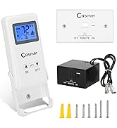
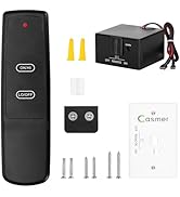

Casmer Fireplace Control
Are our goods of the highest quality?
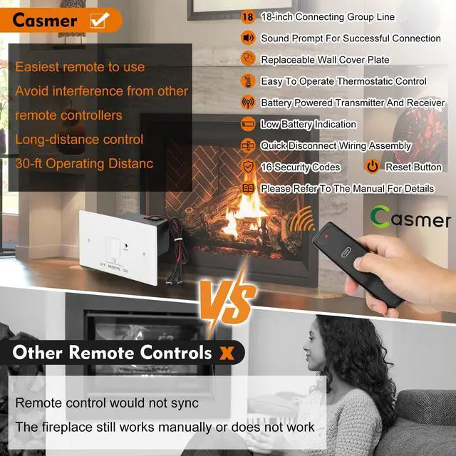
Casmer fireplace remotes are constructed from high - quality materials and incorporate advanced technology, which endows them with durability and reliable performance.
What makes our product unique?
With just one remote, you can operate multiple fireplace brands, eliminating the need for multiple remotes and compatibility headaches. This unlocks limitless comfort, making your fireplace usage more convenient and enjoyable.
UN3 con-th sr-1001
Latching Solenoid & Servo Motor Gas Valve Fireplace Control


Servo Motor-Controlled Latching Solenoid
CASMER Gas Fireplace Remote Control Kit
To power up to a DC servo motor or solenoid valve such as those used with gas valves used in some heater rated gas logs, gas fireplaces and other gas heating appliances.

To power up to a DC servo motor or solenoid valve.Gas fireplace remote control
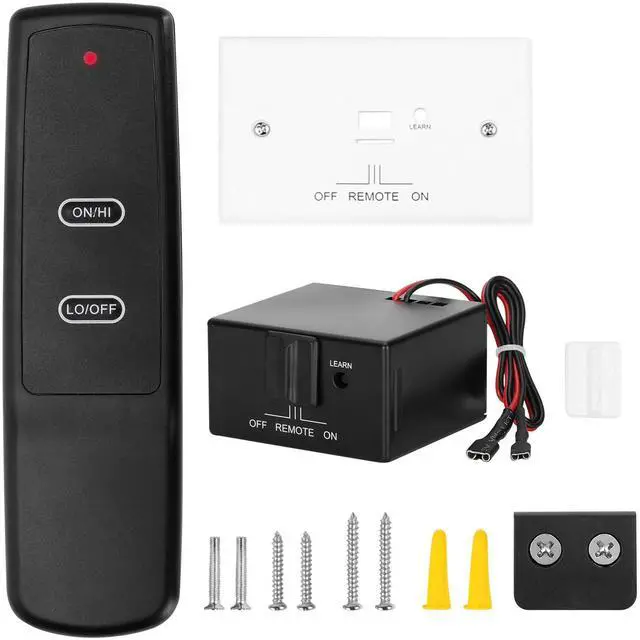
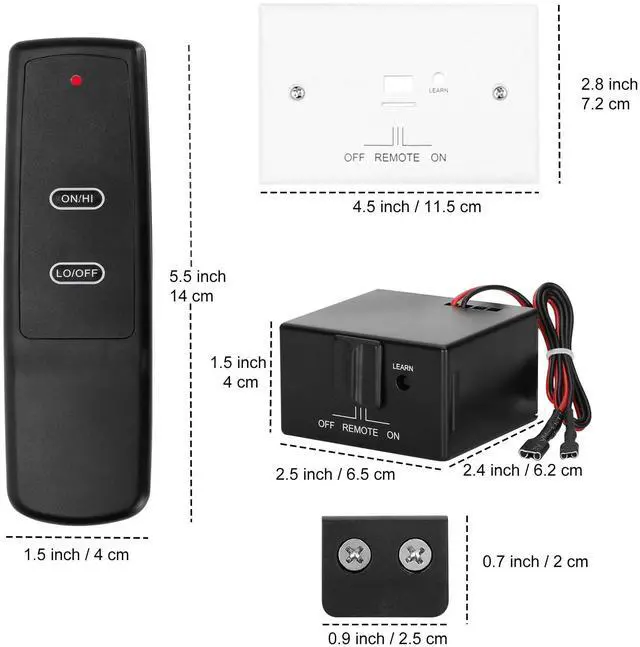
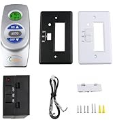
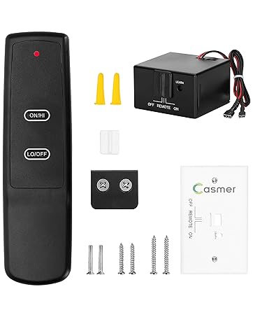
Receiver 1 White Color Slide Button 1 White Color Wall Cover Plate 1
Wiring Assembly – 18” Inches 1 Installation Instructions 1
#6 3/4 Screws (for Wall Cover Plate and Remote control) 4
#6 3/4 Screws (for fireplace system control covers) 2
Plastic wall anchors (for installing transmitter) 2
Latching Solenoid Fireplace Remote Control
sky-con/sky-con-th/sky-mrck/sky-mrck-th/realfyre g10/allen roth:vfl3-r024drlcon1001th/rc400
for pro com vent free gas stove(rg04-1t)cedar ridge hearth:crhsd25rt/ heat&glo cosmo42-ift-b
for rasmussen alterna vent fireballs burner kit (afb30-na-afb30-se-b-n)(afb 30-na-afb 30-ei-b-n)
for orks with compatible heat n glo(esc-42-st-ift/ phoenix42-ift/true-36s-ift/true-36tg-ift/true-36g-ift/ true-42s-ift/true-42tg-ift/true-42g-ift)/ heatilator/majestic/outdoor lifestyles and vermont castings fireplaces

Multiple Styles To Choose From
 Locking Solenoid Valve |  Millivolt Solenoid Valves |  Millivolt Solenoid Valves |  Millivolt Solenoid Valves |  Millivolt Solenoid Valves |  Millivolt Solenoid Valves | |
|---|---|---|---|---|---|---|
Customer Reviews | — | — | — | — | — | — |
Price | — | — | — | — | — | — |
Type of Fireplace Valve | Locking Solenoid Valve | Millivolt Solenoid Gas Valve | Millivolt Solenoid Gas Valve | Millivolt Solenoid Gas Valve | Millivolt Solenoid Gas Valve | Millivolt Solenoid Gas Valve |
Replace Protective Fix Plate | White Plate-Easy installation | White Plate-Easy installation | White Plate-Easy installation | White Plate-Easy installation | White Plate-Easy installation | White Plate-Easy installation |
Adjusting Flame Size | ? | ? | ? | ? | ? | ? |
Temperature Regulation | ? | ? | ? | ? | ? | ? |
Child Protection | ? | ? | ? | ? | ? | ? |
WIRING INSTRUCTIONS
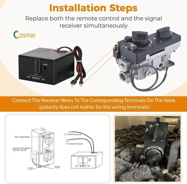
1. Connect the BLACK UL2468-20AWG stranded wire with the 3/16” female terminal from the receiver to the 3/16” male terminal on the valve servo motor.
2. Connect the RED UL2468-20AWG stranded wire with the 1/4” female terminal from the receiver to the 1/4” male terminal on the valve servo motor. NOTE: The 1/4” female terminal may need to be replaced if your connection does not adequately fit the 7/32” terminal.
3. After receiver wires are connected to the valve servo motor terminals make sure the receiver shield is located over the receiver and then locate the receiver in an area that will not exceed the 130° F.
4. Depending on the product that this remote control system is used on, the 3/16” female terminal and wire from the receiver and the 1/4” female terminal and wire may need to be cut to a shorter length. This can be done by removing the (2) wires from the receiver cutting them to the desired length then reinstalling them into the same connections on the receiver.
IMPORTANT NOTE: Operation of these controls is dependent on which wire is attached to which terminal. If operation of control does not correspond to operating buttons on transmitter, reverse wire installation at the receiver or at the control.
5.This fireplace remote control kit only allows for the opening and closing of the fireplace, does not have temperature detection and LCD screen, cannot achieve special functions such as temperature adjustment, constant temperature, child protection, etc., cannot achieve timing function, cannot turn on the fireplace fan or ventilation function. For specific models, only partial function replacement can be achieved. Please choose carefully.
NOTE: Up to 6 VDC of power is provided at the receiver terminal.
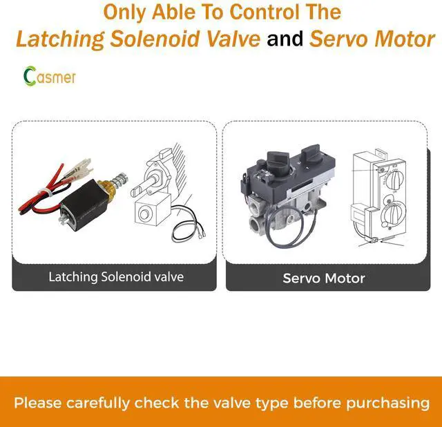
A solenoid valve is controlled with an electric current through the solenoid to allow/restrict the flow of gas;More voltage is needed to quickly open.Where it makes use of latching magnets that secure the solenoid in the open position, the "latching" solenoid doesn't require a constant electric current to stay open/closed.The remote control receiver box does send voltage to the solenoid in order to control the opening/closing of the valve.


Casmer Fireplace Control
Casmer: Universal fireplace remotes for effortless control. Smart,compatible,and user-friendly—bringing convenience and warmth to home
Revolutionize Your Fireplace Experience!
From Flickering Flames to Intense Heat, Our Universal Remote Brings Effortless Control and Endless Comfort.
It's Compatible with more than the Leading Brands.
With Just One Device, You Get a Myriad of Compatible Brands and Comfort Right at Your Fingertips, Unlocking Unlimited Comfort Possibilities.
Casmer Fireplace Control
Casmer Fireplace Control
Are our goods of the highest quality?
Casmer fireplace remotes are constructed from high - quality materials and incorporate advanced technology, which endows them with durability and reliable performance.
What makes our product unique?
With just one remote, you can operate multiple fireplace brands, eliminating the need for multiple remotes and compatibility headaches. This unlocks limitless comfort, making your fireplace usage more convenient and enjoyable.
UN3 con-th sr-1001
Latching Solenoid & Servo Motor Gas Valve Fireplace Control

CASMER Gas Fireplace Remote Control Kit
To power up to a DC servo motor or solenoid valve such as those used with gas valves used in some heater rated gas logs, gas fireplaces and other gas heating appliances.
CONTENTS OF KIT
To power up to a DC servo motor or solenoid valve.Gas fireplace remote control
Receiver 1 White Color Slide Button 1 White Color Wall Cover Plate 1
Wiring Assembly – 18” Inches 1 Installation Instructions 1
#6 3/4 Screws (for Wall Cover Plate and Remote control) 4
#6 3/4 Screws (for fireplace system control covers) 2
Plastic wall anchors (for installing transmitter) 2
Find type of gas valve you fireplace
Latching Solenoid Fireplace Remote Control
sky-con/sky-con-th/sky-mrck/sky-mrck-th/realfyre g10/allen roth:vfl3-r024drlcon1001th/rc400
for pro com vent free gas stove(rg04-1t)cedar ridge hearth:crhsd25rt/ heat&glo cosmo42-ift-b
for rasmussen alterna vent fireballs burner kit (afb30-na-afb30-se-b-n)(afb 30-na-afb 30-ei-b-n)
for orks with compatible heat n glo(esc-42-st-ift/ phoenix42-ift/true-36s-ift/true-36tg-ift/true-36g-ift/ true-42s-ift/true-42tg-ift/true-42g-ift)/ heatilator/majestic/outdoor lifestyles and vermont castings fireplaces
Multiple Styles To Choose From
Locking Solenoid Valve | Millivolt Solenoid Valves | Millivolt Solenoid Valves | Millivolt Solenoid Valves | Millivolt Solenoid Valves | Millivolt Solenoid Valves |
|---|---|---|---|---|---|
| Customer Reviews | |||||
| — | — | — | — | — | — |
| Price | |||||
| — | — | — | — | — | — |
| Type of Fireplace Valve | |||||
| Locking Solenoid Valve | Millivolt Solenoid Gas Valve | Millivolt Solenoid Gas Valve | Millivolt Solenoid Gas Valve | Millivolt Solenoid Gas Valve | Millivolt Solenoid Gas Valve |
| Replace Protective Fix Plate | |||||
| White Plate-Easy installation | White Plate-Easy installation | White Plate-Easy installation | White Plate-Easy installation | White Plate-Easy installation | White Plate-Easy installation |
| Adjusting Flame Size | |||||
| ? | ? | ? | ? | ? | ? |
| Temperature Regulation | |||||
| ? | ? | ? | ? | ? | ? |
| Child Protection | |||||
| ? | ? | ? | ? | ? | ? |
| Battery | 2 "AAA" and 4 "AA".Due to the limitation of air transportation, we cannot provide batteries. You need to buy them separately. I believe you can buy them in any store. |
|---|---|
| Safe Distance | Please keep a safe distance between the receiving module and the flame to avoid melting. |
| Install | Turn appliance OFF and allow to cool before installing or servicing.Turn appliance OFF( at the appliance or remote receiver) if you are away from your house for a long period of time. |
| Instructions | Follow the instructions carefully during installation. Any modification to the component can cause a fire. |
| Operating Distance | Be sure RECEIVER and TRANSMITTER is within 20 to 25-feet operating range. |
| Operation Temperature | Keep RECEIVER from temperatures exceeding 120° F. Battery life shortened when ambient temperatures are above 115° F. |
| Note | Placing the receiver in a metal box and having a low battery will result in a shorter operating distance. |
| For Use Model | legacy42-ift heir36-ift heir42-ift heir50-ift jade32in jade42in jade42ic odfortg-36 odmezg-36 indvr-ift-bd indvr-ift-cb radvt-ift-bd radvt-ift-bm radvt-ift-bs radvt-ift-cb sddvt-ift-bd sddvt-ift-bm sddvt-ift-bd sddvt-ift-bs sddvt-ift-cb heat n glo part # srv2326-110 & 2326-110 oem hht part |
| For Use Model | ch03-r con-th-gda vfl3-ro24drl pleasant hearth vff2-ph 32dr ghp 80-05-102 vff2_ph32drb ser 1926asq2067 |
| For Use Model | For superior (drl2000 drl3500 drl2035ten drl2045ten drl2055ten drl3535ten drl3545ten drl3555ten) |
| For Use Model | For maxitrol gv34 valve (gv34-b1a0n5hl-0001) american gas log 24-in 67000-btu burner kit-burner vented gas fireplace logs and remote(item #5455857 | model #aw24lw2pss101r) |
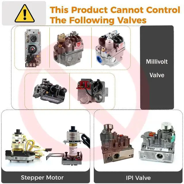
| Troubleshooting | 1. This product can only control Latching Solenoid Valve and Servo Motor. If your fireplace is controlled by a millivolt valves, this product will not meet your needs. 2. Due to different brands using different communication protocols, please replace both the remote control and signal receiver simultaneously. |
| Troubleshooting | 3.The remote control and receiver cannot be paired, or if not used for a long time, the remote control cannot control the fireplace.Please turn the 'sliding switch' to the 'ON' and 'OFF' positions respectively to check if the fireplace can work as expected. If it can work normally,turn the 'sliding switch' to the 'REMOTE' position in the middle,use the pen tip to long press the "LEARN" button on the receiver until it emits a 'beep' sound,and then long press the 'ON' button on the remote control |
| Troubleshooting | 4.The remote control may not work due to low battery power. Please check the battery status periodically. |
| Troubleshooting | Press the “ON” button to turn off the fireplace; press the “OFF” button to turn it on. This indicates the valve logic differs from normal operation. Please provide photos of the valve and receiver for further diagnosis. |
| Installation Steps | 1. Remove the old receiver. 2. Connect the wires from the new receiver to the valve's terminals. 3. Install new batteries. Slide the receiver's “Slide Switch” to both “ON” and “OFF” positions. Observe if the fireplace operates normally. If functioning correctly, press and hold the remote's ‘ON’ button. When the receiver emits a “beep-beep” sound, the remote and receiver are successfully paired and ready for use. 4. If pairing fails, proceed to Step 2 of “Troubleshooting”. |
WIRING INSTRUCTIONS
1. Connect the BLACK UL2468-20AWG stranded wire with the 3/16” female terminal from the receiver to the 3/16” male terminal on the valve servo motor.
2. Connect the RED UL2468-20AWG stranded wire with the 1/4” female terminal from the receiver to the 1/4” male terminal on the valve servo motor. NOTE: The 1/4” female terminal may need to be replaced if your connection does not adequately fit the 7/32” terminal.
3. After receiver wires are connected to the valve servo motor terminals make sure the receiver shield is located over the receiver and then locate the receiver in an area that will not exceed the 130° F.
4. Depending on the product that this remote control system is used on, the 3/16” female terminal and wire from the receiver and the 1/4” female terminal and wire may need to be cut to a shorter length. This can be done by removing the (2) wires from the receiver cutting them to the desired length then reinstalling them into the same connections on the receiver.
IMPORTANT NOTE: Operation of these controls is dependent on which wire is attached to which terminal. If operation of control does not correspond to operating buttons on transmitter, reverse wire installation at the receiver or at the control.
5.This fireplace remote control kit only allows for the opening and closing of the fireplace, does not have temperature detection and LCD screen, cannot achieve special functions such as temperature adjustment, constant temperature, child protection, etc., cannot achieve timing function, cannot turn on the fireplace fan or ventilation function. For specific models, only partial function replacement can be achieved. Please choose carefully.
NOTE: Up to 6 VDC of power is provided at the receiver terminal.
A solenoid valve is controlled with an electric current through the solenoid to allow/restrict the flow of gas;More voltage is needed to quickly open.Where it makes use of latching magnets that secure the solenoid in the open position, the "latching" solenoid doesn't require a constant electric current to stay open/closed.The remote control receiver box does send voltage to the solenoid in order to control the opening/closing of the valve.


