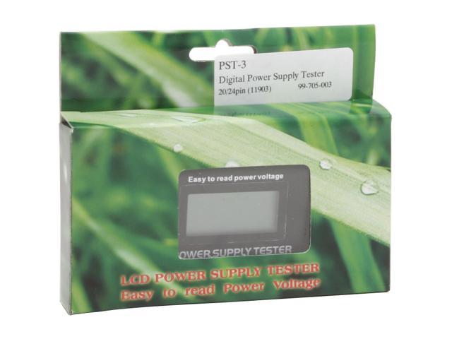
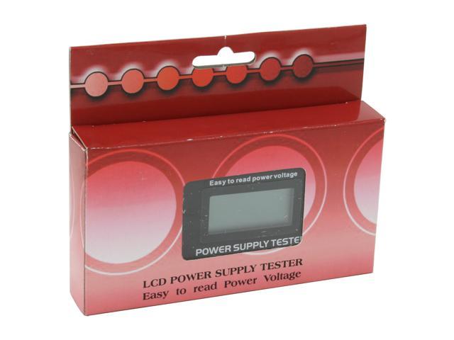
Rexus PST-3 Digital Power Supply Tester with LCD
A quick and easy solution for troubleshooting your PSU issues
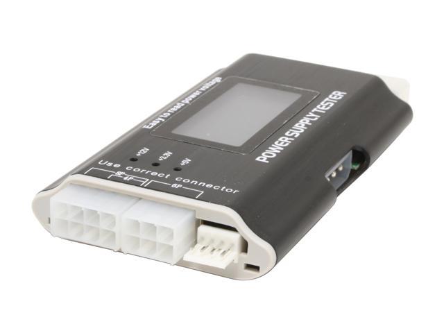
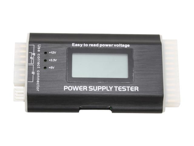
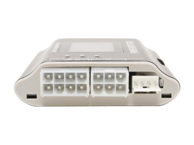
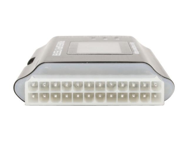
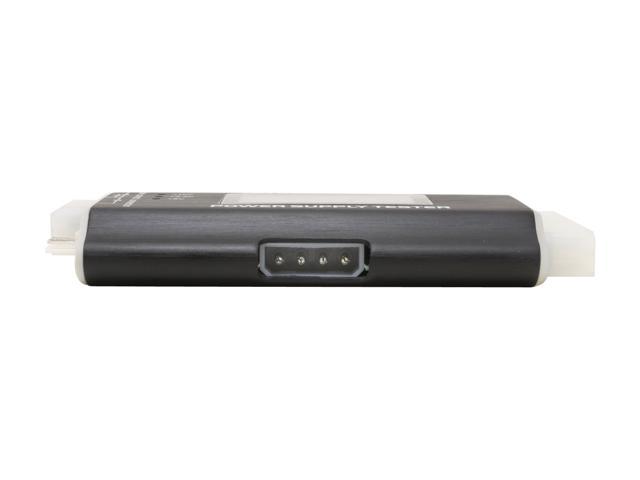
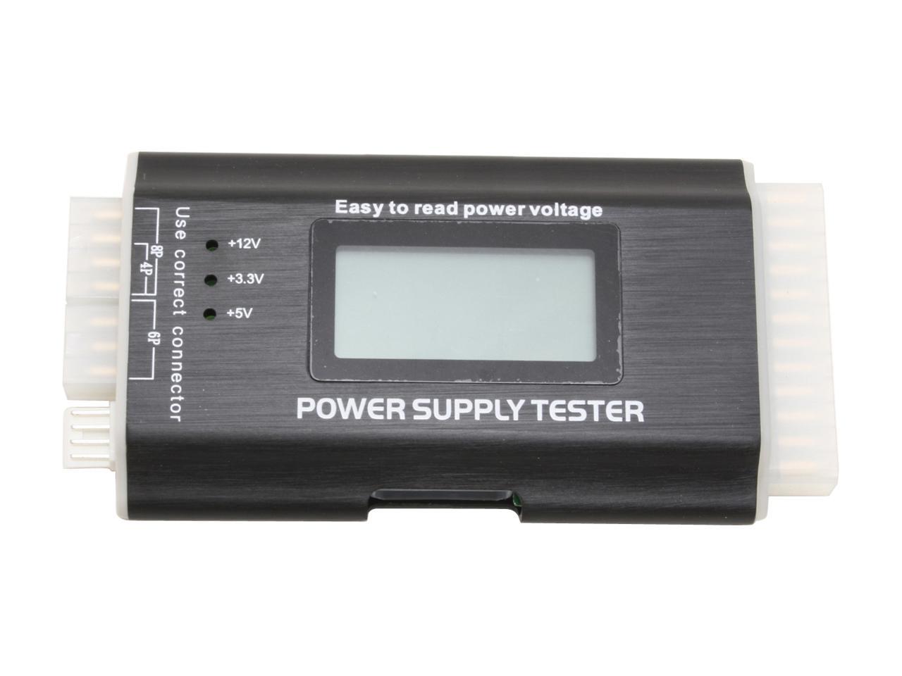
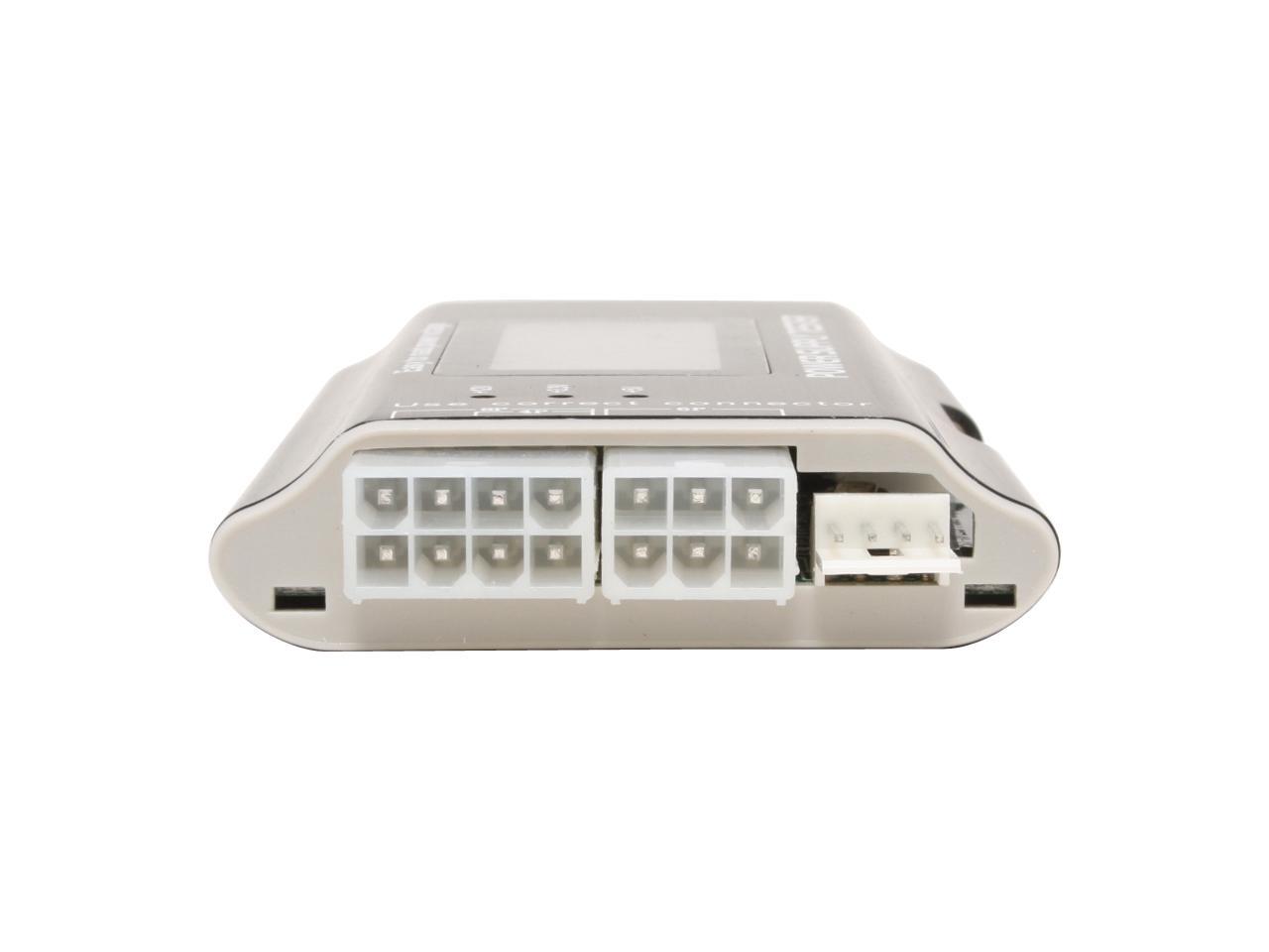
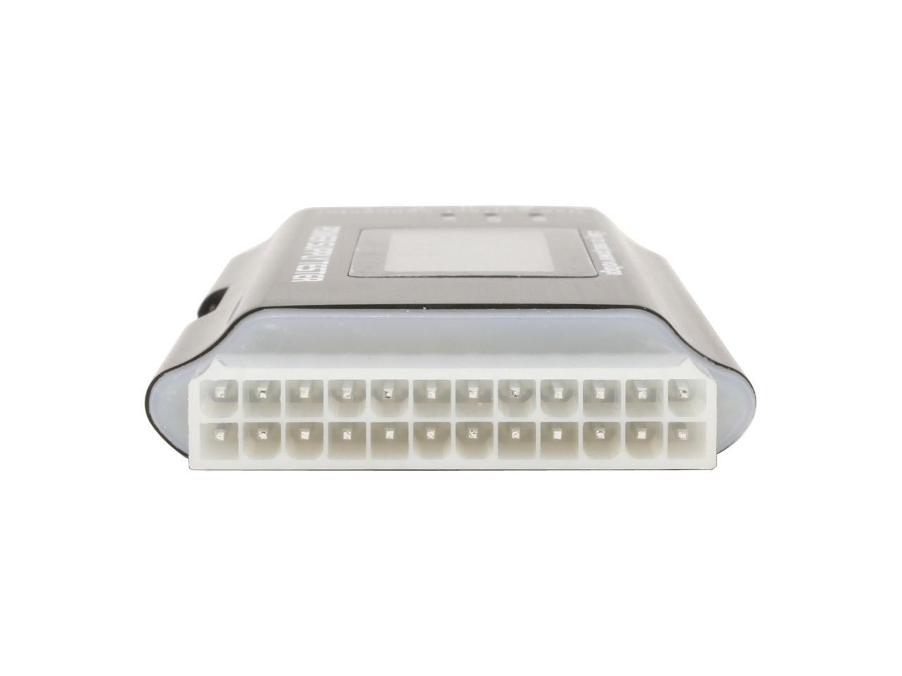
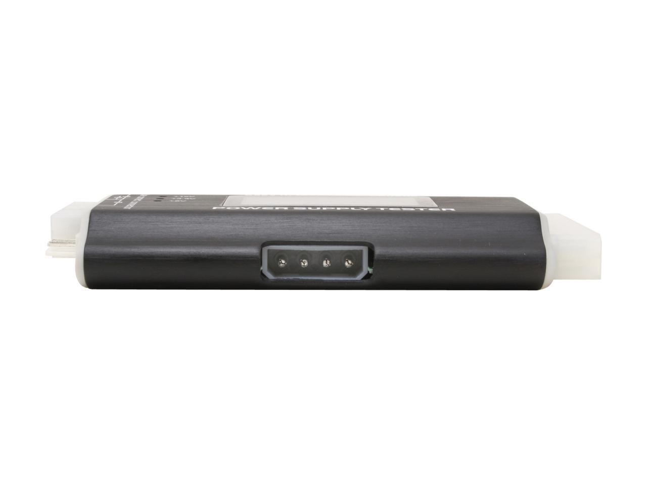
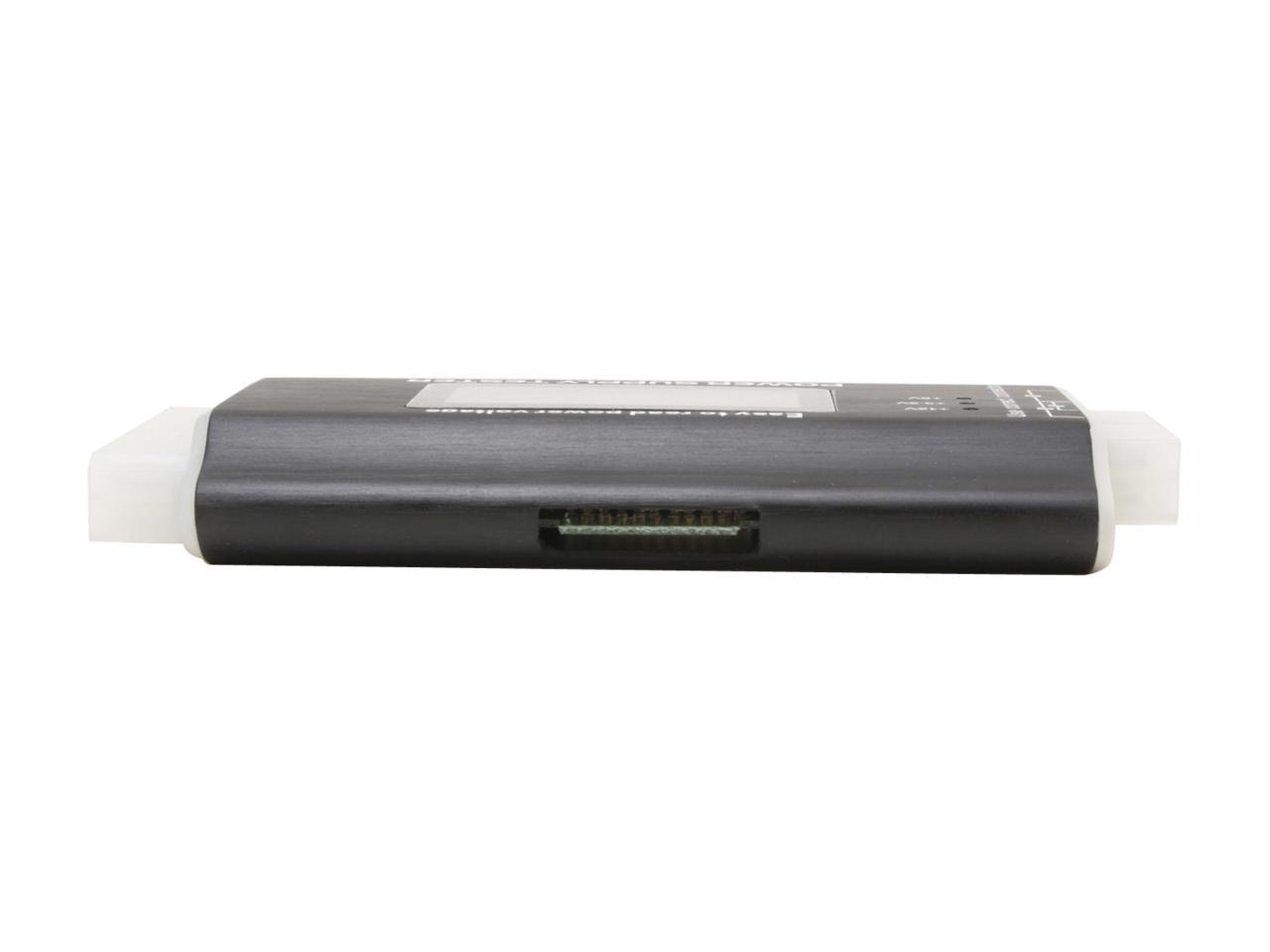
The Rexus PST-3 power supply tester is a must-have for DIY enthusiasts or those working on computers for a living. It connects to the PSU's output connectors, measures the voltage, and displays the results on a backlit LCD screen - instead of having just LEDs indicating the status. It supports today's popular connectors, including 20+4-pin, 4+4-pin for CPU, 6-pin PCIe, 4-pin Molex, SATA and 4-pin fan power connectors. It also displays the Power Good (PG) value on the lower right hand corner. It is the delay in time between the DC rails stabilizing and the Power Good signal being issued for the system to boot, without this signal a system will be unable to boot. Plus, this gadget is compact, lightweight, and rugged built with metal housing, making the Rexus PST-3 power supply tester with LCD a durable and portable solution you can count on to troubleshoot power supply issues at home or in the field.
-
ATX PSU each output connectors check
-
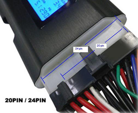
Tests 20-pin and 24-pin power supplies
-
Tests SATA power
-
Tests Pentium 4 power connector
-
Tests PCI-Express power connectors
-
Tests Xeon power connectors
-
Tests Floppy drive connectors
-
Tests standard 4-pin power supply connectors
-
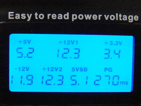
Accurate voltage indicator +/-V(+12V1/+5V/+3.3V/5VSB/+12V2/-12V)
-
ATX P.G value display.
-
Lower or higher P.G values alarm
-
Lower voltage detected alarm
-
Over voltage alarm
-
No voltage detected alarm
How to use
-
Plug-in 24pin and plug-in (P4 / P6 or P8) connector into the tester before turn on power.
-
20pin ATX PSU: use P4 connector.
-
24pin ATX PSU: use P6 connector.
-
EPS PSU: use P8 connector.
-
Turn on your power supply
-
LCD show each voltage and P.G value on the screen automatic and you can hear 2 beep sounds.
-
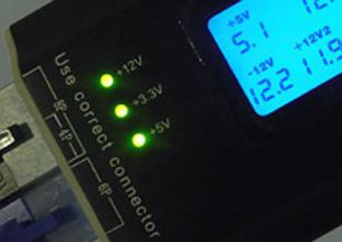
ATX power output connector checking one by one.
-
If power output is working, the LED will light on
-
If power output failed, the LED will not light on.
-
Plug-in (HDD/Floppy) connector and check LED light. (+12V1/+5V).
-
Plug-in SATA connector and check LED light (+12V1/+5V/+3.3V).
-
Remove the connector after your checking.
-
DO NOT plug-in 2 connectors in to the tester at the same time. ( Only 24pin and (P4/P6/P8)
-
Abnormal voltage detected will not display on the screen.
-
No voltage detect, "LL" will display on the screen.
-
Detected Voltage lower than Min. value, "LL" will display on the screen.
-
Detected voltage higher than Max. value, "HH" will display on the screen.
-
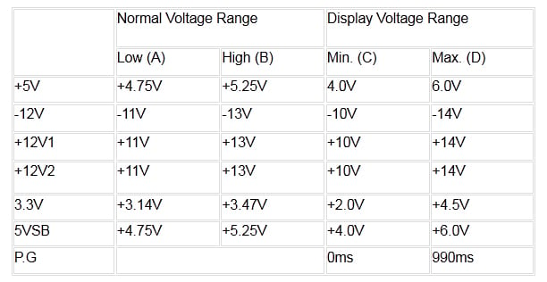
When detected voltage is lower than table value (A), will alarm.
-
When detected voltage is higher than table value (B), will alarm.
-
P.G value detected lower 100ms or higher 900ms, P>G value is abnormal and alarm.
When abnormal happened, it will alarm and relative readouts blink on the screen.
Please Note:
Each voltage normal range:
-
Reference field Low (A) and High (B)
-
+/-5%: +5V, +5VSB, +3.3V
-
+/-10%: +12V1, +12V2, -12V
The -5V DC output is taken off from Intel ATX12V design guide since the 1.2 version.
-
The -5V usage was for last generation ISA slot. But the old ISA had been phased out since 1993~1994.
-
Neither P3 nor P4 systems will need -5V output.