

Your Browsing History
- Free 30-day Returns
$101.99

Meet Your Seller

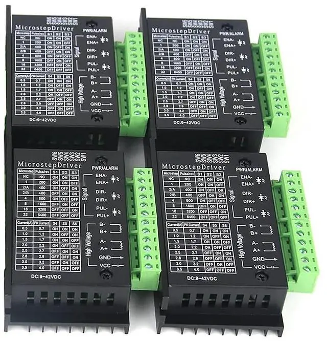
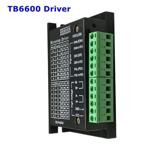
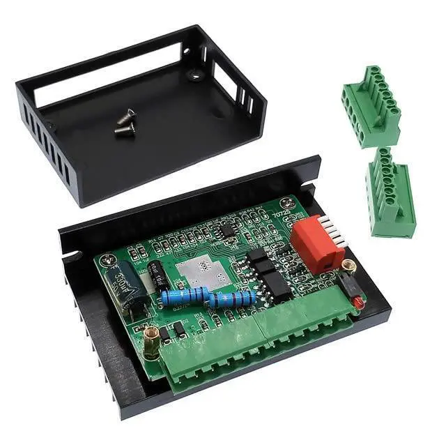
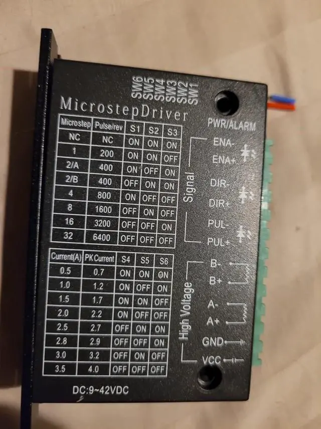
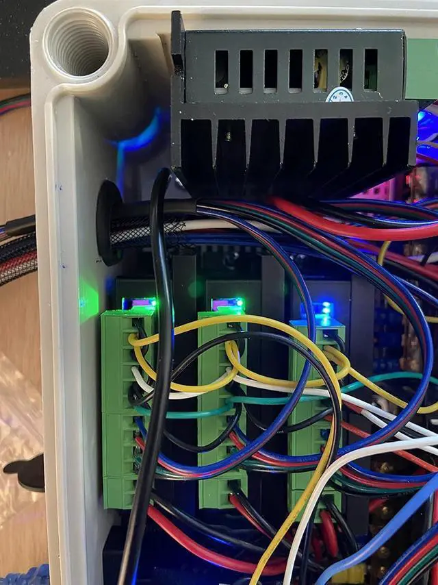
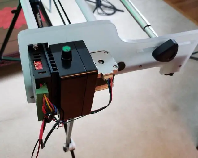


4 Pack TB6600 Stepper Motor Driver, Nema 17/23/34 Stepper Motor CNC Controller, 4A 9-42V Stepper Motor Controller for 42/57/86 Stepper Motor, Single Axes Two Phase Hybrid
- TB6600 stepper motor driver suitable for 86/57/42 type two-phase hybrid stepping motor with phase current below 4.0A, Nema 17 23 34 Stepper Motor Driver (42x42mm to 60x60mm)
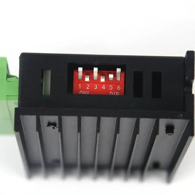
- Set 7 kinds of subdivisions (1/2A/2B/4/8/16/32) through 6-bit DIP switch
- 8 gear output current (0.5A/1.0A/1.5A/2.0A/2.5A/2.8A/3.0A/3.5A)
+
+
Overview
Specs
Reviews

Any questions? Our AI mode will help you find out quickly.
Try me now
Best application is to 57 stepper motors and 42 stepper motors with a torque of 1.8N. m and below
Widely used in various small and medium-sized automation equipment and hardware, such as engraving machine, marking machine, cutting machine, laser phototypesetting, plotter, CNC machine tool, crystal grinding machine, automatic assembly equipment, etc
Technical
Input Voltage 9~42V DC
Input/Output Current 0.5 ~ 3.5A
Maximum Power 150W
Microstepping Options 1, 2, 4, 8, 16, 32
Operating Temperature -10~45°C
Storage Temperature -40~70°C
Humidity Non-condensing, non-waterproof
Warning Keep away from combustible gases and electricity hazards
Wiring Instructions
1. Input Signals
Step pulse signal: PUL+, PUL-/Direction
level signal: DIR+, DIR-/Offline
signal: EN+, EN- (can be left unconnected)
1.2 Connection Methods
Common Anode Connection: Connect PUL+, DIR+, EN+ to the control system power supply/Connect pulse signal through PUL-, direction signal through DIR-, enable signal through EN-
Common Cathode Connection: Connect PUL-, DIR-, EN- to the control system ground/Connect pulse signal through PUL+, direction signal through DIR+, enable signal through EN+/Add current-limiting resistors R if required (same as common anode connection)
1.3 Complete System Wiring
Connect the driver to the controller via the signal terminals/Connect the 4-wire stepper motor to A+, A-, B+, B- terminals/Connect the DC power supply (12-42V) to VCC and GND terminals
1.4 Critical Wiring Notes
Always disconnect power before wiring/Ensure motor wires are correctly phased and no internal short circuits exist/Incorrect wiring will permanently damage the driver
Offline Function
When offline function is activated (EN terminal valid), the motor rotor becomes free and unlocked for manual rotation
Input pulse signals will be ignored during offline mode
Deactivate offline function to resume normal automatic control
Quick Start Guide
Set DIP switches to 16 microstepping and appropriate current for your motor
Connect power supply, motor and controller correctly
Connect only the pulse signal PUL (set frequency below 1KHz initially)
Keep offline function disabled
Power on - motor will rotate forward by default
After successful operation, test acceleration, direction, microstepping and offline functions sequentially
Do I need series resistors for control signals above 5V?
No, upgraded driver supports 3.3V -24V control signals directly.
Power indicator is on but motor does not rotate
Ensure control interface provides at least 5mA drive capability (common issue with single-chip microcomputer IO ports).
How to identify stepper motor phase wires?
Short any two wires - if manual rotation of motor rotor feels resistant, these two wires belong to the same phase (connect to A+/A-). The remaining two wires form the other phase (connect to B+/B-).
Motor rotation direction is reversed
Simply swap the two wires of either phase (A+ & A- or B+ & B-).
Widely used in various small and medium-sized automation equipment and hardware, such as engraving machine, marking machine, cutting machine, laser phototypesetting, plotter, CNC machine tool, crystal grinding machine, automatic assembly equipment, etc
Technical
Specifications
Input Voltage 9~42V DC
Input/Output Current 0.5 ~ 3.5A
Maximum Power 150W
Microstepping Options 1, 2, 4, 8, 16, 32
Operating Temperature -10~45°C
Storage Temperature -40~70°C
Humidity Non-condensing, non-waterproof
Warning Keep away from combustible gases and electricity hazards
Wiring Instructions
1. Input Signals
Step pulse signal: PUL+, PUL-/Direction
level signal: DIR+, DIR-/Offline
signal: EN+, EN- (can be left unconnected)
1.2 Connection Methods
Common Anode Connection: Connect PUL+, DIR+, EN+ to the control system power supply/Connect pulse signal through PUL-, direction signal through DIR-, enable signal through EN-
Common Cathode Connection: Connect PUL-, DIR-, EN- to the control system ground/Connect pulse signal through PUL+, direction signal through DIR+, enable signal through EN+/Add current-limiting resistors R if required (same as common anode connection)
1.3 Complete System Wiring
Connect the driver to the controller via the signal terminals/Connect the 4-wire stepper motor to A+, A-, B+, B- terminals/Connect the DC power supply (12-42V) to VCC and GND terminals
1.4 Critical Wiring Notes
Always disconnect power before wiring/Ensure motor wires are correctly phased and no internal short circuits exist/Incorrect wiring will permanently damage the driver
Offline Function
When offline function is activated (EN terminal valid), the motor rotor becomes free and unlocked for manual rotation
Input pulse signals will be ignored during offline mode
Deactivate offline function to resume normal automatic control
Quick Start Guide
Set DIP switches to 16 microstepping and appropriate current for your motor
Connect power supply, motor and controller correctly
Connect only the pulse signal PUL (set frequency below 1KHz initially)
Keep offline function disabled
Power on - motor will rotate forward by default
After successful operation, test acceleration, direction, microstepping and offline functions sequentially
Do I need series resistors for control signals above 5V?
No, upgraded driver supports 3.3V -24V control signals directly.
Power indicator is on but motor does not rotate
Ensure control interface provides at least 5mA drive capability (common issue with single-chip microcomputer IO ports).
How to identify stepper motor phase wires?
Short any two wires - if manual rotation of motor rotor feels resistant, these two wires belong to the same phase (connect to A+/A-). The remaining two wires form the other phase (connect to B+/B-).
Motor rotation direction is reversed
Simply swap the two wires of either phase (A+ & A- or B+ & B-).
Warranty & Returns
Warranty, Returns, And Additional Information
Warranty
- Please contact the Seller directly for warranty information. Warranty information may also be found on the Manufacturer's website.
- CONTACT
Return Policies
- Return for refund within: 30 days
- Return for replacement within: 30 days
- This item is covered by Grandwood Tech Limited Return Policy
Manufacturer Contact Info
- For a directory of all our manufacturers, please click below.
- Manufacturers Directory
LOADING...