Your Browsing History
- Free 30-day Returns
$489.99
Ships from Taiwan.

Meet Your Seller


Visit Innocard Store
FOLLOW
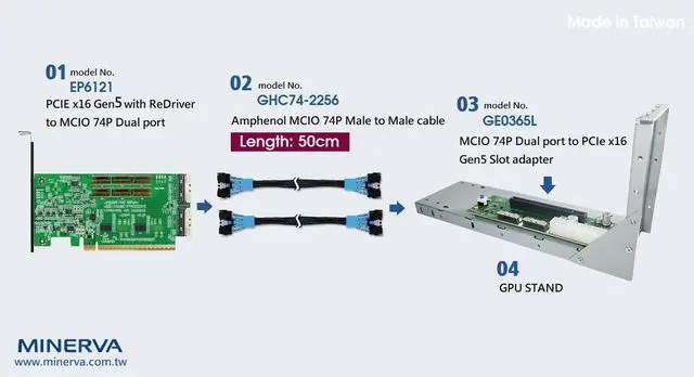
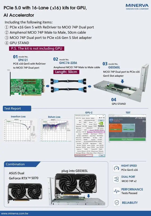
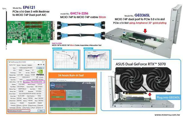
PCIe x16 Gen5 with Redriver to MCIO 74P Daul port with MCIO 74P Cable 50cm with MCIO 74P Daul port to PCIe x16 Gen 5 Slot adapter
- www.minerva.com.tw
- Designed / Made in Taiwan
+
+
Overview
Specs
Reviews
Any questions? Our AI beta will help you find out quickly.
Try me now
Specification
- MCIO 74P dual port to PCIe x16 Gen5 convert
- Built-in MCIO 74P dual port connectors with 30u(0.38um) min Au mating area plating
- Input PCIe CEM +12V power with TVS protection, 400W Peak Pulse Power Dissipation
- PCIe CEM +12V power with high side protection controller to enable N-MOS FET for 12V, 5A output
- PCIe CEM +12V PWM buck to 3.3V, 5A output with Eco-mode
- 3.3V, 5A Load Switch With Automatic Restart after Supervisor Fault Detection when Enabled to protect PCIe 5.0 ReDriver controller
- Input PCIe CEM power 3.3Vaux with Load Switch protection for Bus Buffer IC.
- Built-in ReDriver controller to extend PCIe 5.0, 32GT/s 16 lanes signals and may provide programmable linear equalization, flat gain.
- ReDriver CTLE boosts up to 22 dB at 16 GHz
- The PCIe 16 lanes can be bifurcated into four x4 link width to support different system topologies
- Built-in PCIe 100MHz clock buffer(Address: 0x6C) for MCIO 74P dual port to drive PCB more trace reach and longer cable length.
- Built-in SMBus Switch(Address: 0x70) with Reset funtion for MCIO 74P dual port SMBus communication
- Built-in SMBus I/O Expander(Address: 0x20) for OOB(out of band) management to remote MCIO 74P dual port Reset signals
- Built-in PERST# Bus Buffer Gate to be used in PCB more trace reach and longer cable length.
- Supports PCIe PERST# for OOB(out of band) management to remote MCIO 74P dual port Reset signals.
- Built-in WAKE# Bus Buffer Gate to be used in PCB more trace reach and longer cable length.
- Built-in CLKREQ# Bus Buffer Gate to be used in PCB more trace reach and longer cable length.
- LED1 Green ON indicates +12V ready
- LED2 Green ON indicates +3.3V ready
- LED3 Green ON indicates Vaux ready
- LED4 Red ON indicates Input +12V Error
- LED5 Red OFF indicates PERST# Normal (Function intentionally inverted)
- LED6 Red OFF indicates WAKE# Normal (Function intentionally inverted)
- LED7 Red OFF indicates CLKREQ# Normal (Function intentionally inverted)
- LED8 Green ON indicates Add-in card presnt
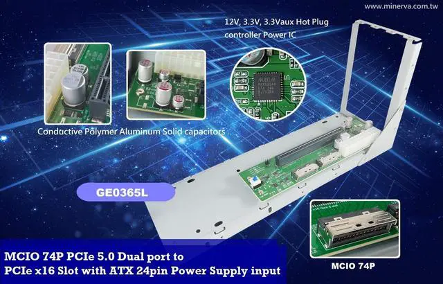
- MCIO 74P dual port to PCIe x16 data link width convert
- Built-in MCIO 74P connector x2pcs with 30u(0.76um) min Au mating area plating
- Built-in PCIe 5.0 x16 Slot with 30u(0.76um) min Au mating area plating
- Built-in ATX 24-pin Power supply connector
- +5VSB Input with Bidirectional TVS(TRANSIENT VOLTAGE SUPPRESSOR)
- Manul Switch ON or Jumper Short for ATX 24-pin Power supply ON
- Built-in MAX5954A PCI Express Power Hot-Plug Controller
- Hot Swaps +12V, +3.3V, and 3.3V Auxiliary Power Rail
- Active Current Limiting Protects Against Overcurrent/ Short-Circuit Conditions
- Drives two external n-channel MOSFETs to control the +12V and +3.3V main outputs
- Built-in Conductive Polymer Aluminum Solid Capacitors
- For 75W PCIe x16 Slot Power Supply Rail Requirements as follows:
- +12V Voltage Supply Current Capacitive Load : 5.5 A current, 1470 F
- +3.3 Voltage Supply Current Capacitive Load : 3 A current, 2300 F
- 3.3aux Voltage Supply Current Capacitive Load : 375 mA current, 330 F
- Built-in PCIe PERST# Bus Buffer & Programmable-Delay Supervisory Circuit
- Built-in PCIe WAKE# Auto-Bidirectional Multi-Voltage Level Translator
- Built-in PCIe CLKREQ# Auto-Bidirectional Multi-Voltage Level Translator
- Built-in SMBus Hot Swappable Bus and Buffer
- Through MCIO 74P(CN1) B8 pin connects to PCIe x16 Slot B30 pin
- Through MCIO 74P(CN1) A12 pin connects to PCIe x16 Slot B12 pin
- LED1 PCIe +12V power ready
- LED2 PCIe +3.3V power ready
- LED3 PCIe 3.3Vaux power ready
- LED4 ON to OFF indicated PCIe PERST# OK
Warranty & Returns
Warranty, Returns, And Additional Information
Warranty
- Please contact the Seller directly for warranty information. Warranty information may also be found on the Manufacturer's website.
- CONTACT
Return Policies
- Return for refund within: 30 days
- Return for replacement within: 30 days
- This item is covered by Innocard Return Policy
Manufacturer Contact Info
- For a directory of all our manufacturers, please click below.
- Manufacturers Directory
LOADING...