


Description
- This module (Micro SD Card Adapter) is a Micro S D card read and write module. Through the file system and SPI interface driver, the microcontroller system can read and write files in the Micro SD card.
- Ar duino users can directly use the SD card library that comes with the Arduino IDE to complete the initialization, reading and writing of the card.
Features
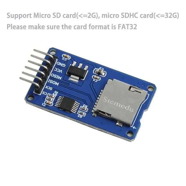
- Support Micro SD card, Micro SD HC card (high speed card)
- Onboard level conversion circuit, that is, the interface level can be 5V or 3.3V
- The power supply is 4.5V~5.5V, and the onboard 3.3V voltage regulator circuit
- Current: 0.2-200mA
- Communication interface: SPI
- 4PCS M2 screw positioning holes, easy installation
What you will get?
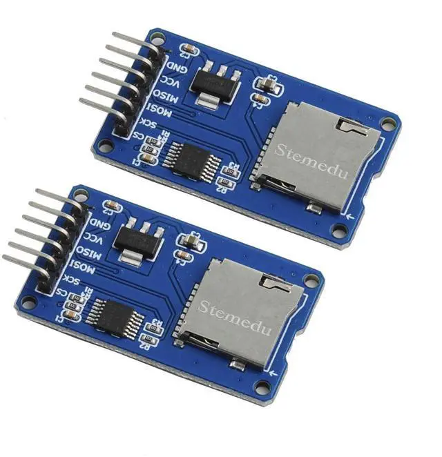
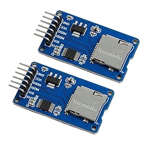
- 2 X Micro SD Card Adapter Module
- Tutorial Support from Stemedu

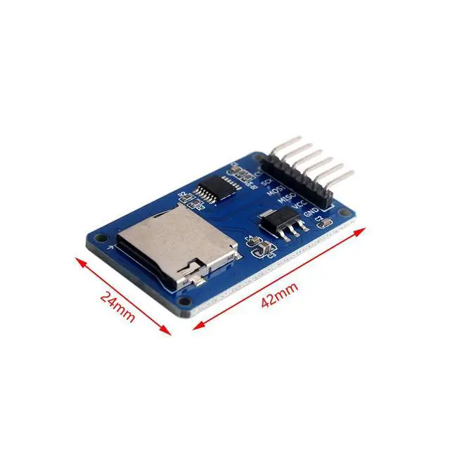
Size: 24mm×42mmx10mm
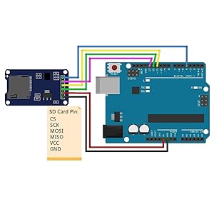
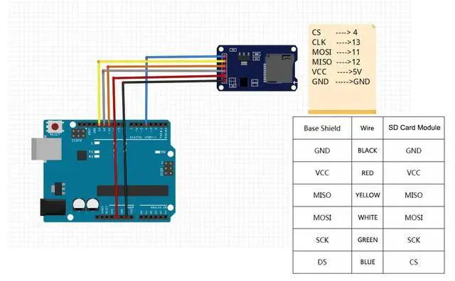
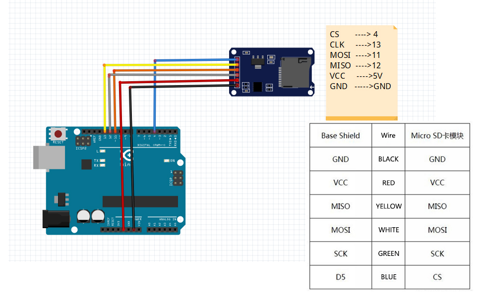
Micro SD Card TF Card Read Write Module and Arduino connection
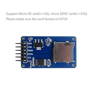
Please make sure the card format is FAT32
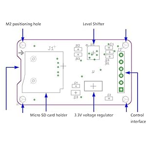
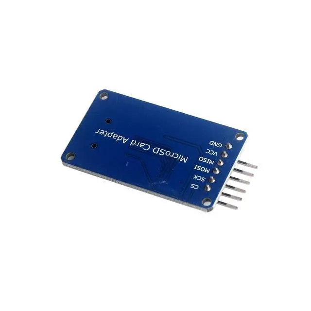
Pin of Micro S D Card TF Card Read Write Module
- Control interface: a total of 6 pins (GND, VCC, MISO, MOSI, SCK, CS), GND is the ground, VCC is the power supply, MISO, MOSI, SCK are the SPI bus, and CS is the chip selection signal pin;
- 3.3V voltage stabilizing circuit: The 3.3V output of the LDO voltage stabilization is the power supply for the level conversion chip and the Micro SD card;
- Level conversion circuit: the signal to the Micro SD card is converted to 3.3V, and the MISO signal from the Micro SD card to the control interface is also converted to 3.3V, which can be read by the general AVR microcontroller system;
- Micro S D card holder: It is a self-elastic card holder, which is convenient for inserting and removing the card.
- Positioning holes: 4 M2 screw positioning holes with a diameter of 2.2mm, which make the module easy to install and position and realize the combination between modules;
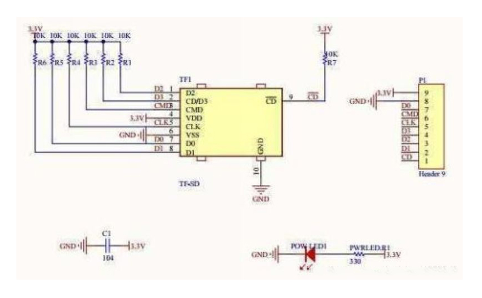
Module electrical schematic diagram of Micro S D Card TF Card Read Write Module
Features
Experiment equipment:
- 1. Arduino-compatible motherboard Catduino (not familiar with open source hardware can be understood as Atmega328P MCU development board) and a mini USB cable;
- 1 x Micro SD card module;
- 1 x Samsung 2G Micro SD card;
- 1 x Arduino interface expansion board Base shield (internal link);
- 6 x female-to-female DuPont wires, used to connect the control interface of the module and the SPI interface from the Base Shield.
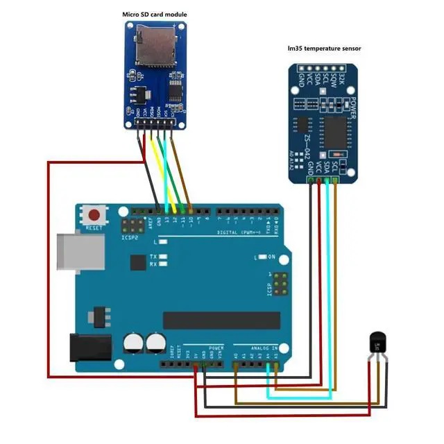
Experimental steps:
- 1. Insert the Base Shield directly into the Catduino motherboard, make sure that the SD card has been formatted as FAT16 or FAT32, and insert it into the SD card module.
- 2. Use 6 female-to-female DuPont wires to connect the SD card module to the SPI interface of the Base Shield
- 3. Connect Catduino with mini USB. If this motherboard is used for the first time, its USB-to-serial driver can be found from the drivers under the Arduino IDE directory.
- 4. The related programs for reading and writing the SD card can use the program that comes with the Arduino IDE, and the directory is...\Arduino-1.0\libraries\SD. Reopen the Arduino IDE, click the Open button on the toolbar, and open the CardInfo routine in SD, as shown in Figure below.
Note that the chip select signal pin should be changed to the chip select pin actually connected to the module. In this experiment Choose D10. Select the serial port and board name, and click the burn button to burn. This example shows how to read the information of the SD card, including the card type, file system type, storage capacity, and also lists the file names in the card. Click Serial Monitor to view it.
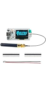 868MHz 915MHz WiFi LoRa 32 V3 Module Development Board Type-C SX1262 Integrat... | 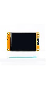 ESP32 2.8inch TFT Touch Screen Display ESP-32S ESP-WROOM-32 | 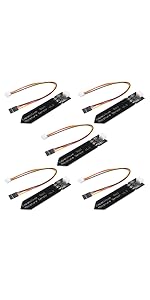 Capacitive Analog Soil Moisture Sensor | 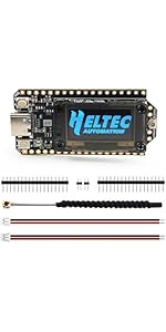 Heltec WiFi LoRa 32 V4 Development Board 0.96" OLED Display with ESP32-S3 SX1... |  Heltec Mesh Node T114 V2 Tracker nRF52840 SX1262 LoRa Bluetooth 5.0 LoRaWAN D... |  HC-SR501 PIR Infrared Sensor | |
|---|---|---|---|---|---|---|
| Customer Reviews | — | — | — | — | — | — |
| Price | — | — | — | — | — | — |
| Product Name | 868MHz 915MHz WiFi LoRa 32 V3 Module Development Board Type-C SX1262 Integrated WiFi Bluetooth - ESP32 0.96 inch OLED Display 8MB Flash IOT Lora Dev-Board + Antenna U.FL IPEX to SMA 915MHz | ESP32 Touchscreen 2.8inch TFT LCD Display ESP-WROOM-32 ILI9341 Resistive Touch Module 240 * 320 ESP32-2432S028R Bluetooth WIFI Dual Core Development Board for Arduino | 5PCS Capacitive Analog Soil Moisture Sensor Module 3.3~5.5V Corrosion Resistant Humidity Detection Sensors DIY Electronic for Arduino Raspberry Pi | Heltec WiFi LoRa 32 V4 Development Board 0.96" OLED Display with ESP32-S3 SX1262 LoRa Chip Long-Range IoT DEV-Board Compatible with Lora V3 for Meshtastic WiFi IoT Devices Arduino Smart Home | Heltec Mesh Node T114 V2 Tracker nRF52840 SX1262 LoRa Bluetooth 5.0 LoRaWAN Development Board Kit 1.14 Inch LCD Screen Display Compatible with Meshtastic Arduino | HC-SR501 PIR Sensor Infrared IR Body Motion Module for Arduino Raspberry Pi(Pack of 5pcs) |
Description
- This module (Micro SD Card Adapter) is a Micro S D card read and write module. Through the file system and SPI interface driver, the microcontroller system can read and write files in the Micro SD card.
- Ar duino users can directly use the SD card library that comes with the Arduino IDE to complete the initialization, reading and writing of the card.
Features
- Support Micro SD card, Micro SD HC card (high speed card)
- Onboard level conversion circuit, that is, the interface level can be 5V or 3.3V
- The power supply is 4.5V~5.5V, and the onboard 3.3V voltage regulator circuit
- Current: 0.2-200mA
- Communication interface: SPI
- 4PCS M2 screw positioning holes, easy installation
What you will get?
- 2 X Micro SD Card Adapter Module
- Tutorial Support from Stemedu
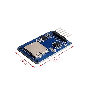
Size: 24mm×42mmx10mm
Micro SD Card TF Card Read Write Module and Arduino connection
Please make sure the card format is FAT32
Pin of Micro S D Card TF Card Read Write Module
- Control interface: a total of 6 pins (GND, VCC, MISO, MOSI, SCK, CS), GND is the ground, VCC is the power supply, MISO, MOSI, SCK are the SPI bus, and CS is the chip selection signal pin;
- 3.3V voltage stabilizing circuit: The 3.3V output of the LDO voltage stabilization is the power supply for the level conversion chip and the Micro SD card;
- Level conversion circuit: the signal to the Micro SD card is converted to 3.3V, and the MISO signal from the Micro SD card to the control interface is also converted to 3.3V, which can be read by the general AVR microcontroller system;
- Micro S D card holder: It is a self-elastic card holder, which is convenient for inserting and removing the card.
- Positioning holes: 4 M2 screw positioning holes with a diameter of 2.2mm, which make the module easy to install and position and realize the combination between modules;
Module electrical schematic diagram of Micro S D Card TF Card Read Write Module
Features
Experiment equipment:
- 1. Arduino-compatible motherboard Catduino (not familiar with open source hardware can be understood as Atmega328P MCU development board) and a mini USB cable;
- 1 x Micro SD card module;
- 1 x Samsung 2G Micro SD card;
- 1 x Arduino interface expansion board Base shield (internal link);
- 6 x female-to-female DuPont wires, used to connect the control interface of the module and the SPI interface from the Base Shield.
Experimental steps:
- 1. Insert the Base Shield directly into the Catduino motherboard, make sure that the SD card has been formatted as FAT16 or FAT32, and insert it into the SD card module.
- 2. Use 6 female-to-female DuPont wires to connect the SD card module to the SPI interface of the Base Shield
- 3. Connect Catduino with mini USB. If this motherboard is used for the first time, its USB-to-serial driver can be found from the drivers under the Arduino IDE directory.
- 4. The related programs for reading and writing the SD card can use the program that comes with the Arduino IDE, and the directory is...\Arduino-1.0\libraries\SD. Reopen the Arduino IDE, click the Open button on the toolbar, and open the CardInfo routine in SD, as shown in Figure below.
Note that the chip select signal pin should be changed to the chip select pin actually connected to the module. In this experiment Choose D10. Select the serial port and board name, and click the burn button to burn. This example shows how to read the information of the SD card, including the card type, file system type, storage capacity, and also lists the file names in the card. Click Serial Monitor to view it.
868MHz 915MHz WiFi LoRa 32 V3 Module Development Board Type-C SX1262 Integrat... | ESP32 2.8inch TFT Touch Screen Display ESP-32S ESP-WROOM-32 |  Capacitive Analog Soil Moisture Sensor | Heltec WiFi LoRa 32 V4 Development Board 0.96" OLED Display with ESP32-S3 SX1... | Heltec Mesh Node T114 V2 Tracker nRF52840 SX1262 LoRa Bluetooth 5.0 LoRaWAN D... |  HC-SR501 PIR Infrared Sensor | |
|---|---|---|---|---|---|---|
| Customer Reviews | — | — | — | — | — | — |
| Price | — | — | — | — | — | — |
| Product Name | 868MHz 915MHz WiFi LoRa 32 V3 Module Development Board Type-C SX1262 Integrated WiFi Bluetooth - ESP32 0.96 inch OLED Display 8MB Flash IOT Lora Dev-Board + Antenna U.FL IPEX to SMA 915MHz | ESP32 Touchscreen 2.8inch TFT LCD Display ESP-WROOM-32 ILI9341 Resistive Touch Module 240 * 320 ESP32-2432S028R Bluetooth WIFI Dual Core Development Board for Arduino | 5PCS Capacitive Analog Soil Moisture Sensor Module 3.3~5.5V Corrosion Resistant Humidity Detection Sensors DIY Electronic for Arduino Raspberry Pi | Heltec WiFi LoRa 32 V4 Development Board 0.96" OLED Display with ESP32-S3 SX1262 LoRa Chip Long-Range IoT DEV-Board Compatible with Lora V3 for Meshtastic WiFi IoT Devices Arduino Smart Home | Heltec Mesh Node T114 V2 Tracker nRF52840 SX1262 LoRa Bluetooth 5.0 LoRaWAN Development Board Kit 1.14 Inch LCD Screen Display Compatible with Meshtastic Arduino | HC-SR501 PIR Sensor Infrared IR Body Motion Module for Arduino Raspberry Pi(Pack of 5pcs) |