

Your Browsing History


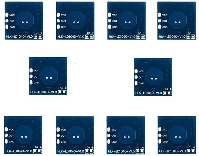
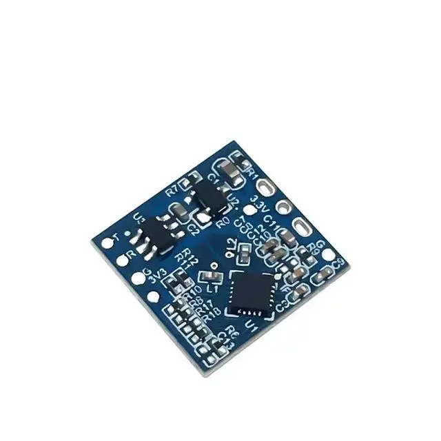
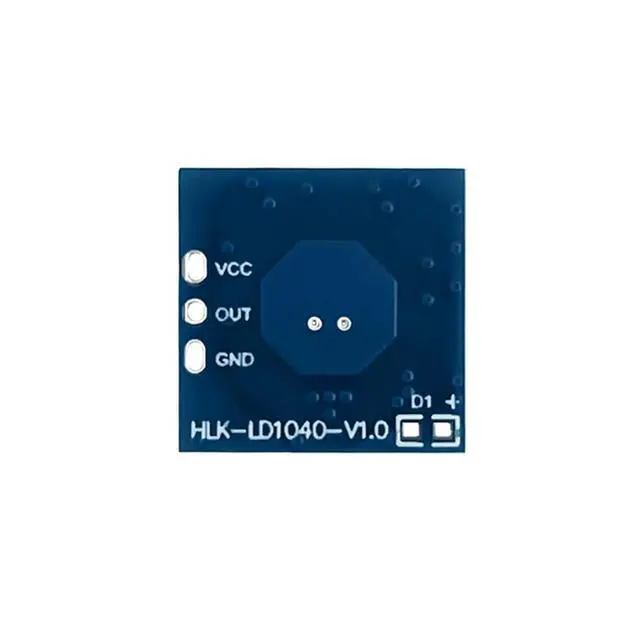
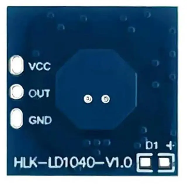
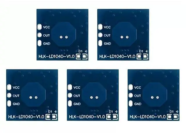


HLK-LD1040 X-Band 10G Micro Motion Intelligent Sensor Low Power Ra·DAR Sensor Module Support Fast Inspection Mode (10Pcs)
Limited time offer, ends 09/06 By StarVelocity Technology
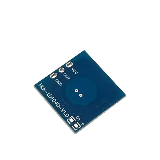
- This is a motion sensing module based on X-band ra·dar chip, with a centre frequency of 10.525GHz.; The design adopts fixed frequency, directional transmitting and receiving antenna (1T1R), integrated IF demodulation, signal amplification and digital processing, with the ability of delay setting, adjustable sensing range and light intensity detection.; Supporting the drive power supply should be 5-1 2V (recommended 5V), drive current is not less than 5mA, the power supply ripple amplitude needs to be controlled within 100mV, frequency fluctuations should be small; Interface type: Hole spacing 2.0/2.54mmx3PIN. O: high and low level outputs. V: 5-1 2V. G: GND, power ground (The other end is the download debugging port); Warm Tips: Drive power and ra·dar module assembly, should avoid ra·dar module bottom or antenna surface, facing the drive power module, and should try to drive away from the power module inside the rectifier bridge, switching transformer and other frequency interference devices, in order to prevent interference with microwave signals.
+
+
Overview
Specs
Reviews

Any questions? Our AI mode will help you find out quickly.
Try me now
HLK-LD1040 X-band 10G Micro Motion Intelligent Sensor Low Power Ra·dar Sensor Module Support Fast Inspection Mode
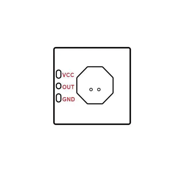
Configuration Interface type: (hole spacing 2.0 / 2.54 mmx3PIN)
V: 5-1 2V
O: high and low level outputs
G: GND, power ground (The other end is the download debugging port) Results may vary with different test environments or moving targets: -Metal casing will have shielding effect on ra·dar electromagnetic wave, affecting the perceived distance; -The above test results are obtained from the standard test site. The above test results are obtained in a standard test site, for specific test environment and conditions, please consult the relevant technical personnel.
Driver power supply design considerations: Be sure to use the output voltage, current and ripple coefficient and other standards of the drive power supply, drive power is not stable, electromagnetic radiation is too strong, will cause false alarms ra·dar module, no perception, cycle of self-start and other phenomena; supporting the drive power supply should be 5-1 2V (recommended 5V), drive current is not less than 5mA, the power supply ripple amplitude needs to be controlled within 100mV, frequency fluctuations should be small; drive power and ra·dar module assembly, should avoid ra·dar module bottom or antenna surface, facing the drive power module, and should try to drive away from the power module inside the rectifier bridge, switching transformer and other frequency interference devices, in order to prevent interference with microwave signals.
Configuration Interface type: (hole spacing 2.0 / 2.54 mmx3PIN)
V: 5-1 2V
O: high and low level outputs
G: GND, power ground (The other end is the download debugging port) Results may vary with different test environments or moving targets: -Metal casing will have shielding effect on ra·dar electromagnetic wave, affecting the perceived distance; -The above test results are obtained from the standard test site. The above test results are obtained in a standard test site, for specific test environment and conditions, please consult the relevant technical personnel.
Driver power supply design considerations: Be sure to use the output voltage, current and ripple coefficient and other standards of the drive power supply, drive power is not stable, electromagnetic radiation is too strong, will cause false alarms ra·dar module, no perception, cycle of self-start and other phenomena; supporting the drive power supply should be 5-1 2V (recommended 5V), drive current is not less than 5mA, the power supply ripple amplitude needs to be controlled within 100mV, frequency fluctuations should be small; drive power and ra·dar module assembly, should avoid ra·dar module bottom or antenna surface, facing the drive power module, and should try to drive away from the power module inside the rectifier bridge, switching transformer and other frequency interference devices, in order to prevent interference with microwave signals.
Warranty & Returns
Warranty, Returns, And Additional Information
Warranty
- Please contact the Seller directly for warranty information. Warranty information may also be found on the Manufacturer's website.
- CONTACT
Return Policies
- Return for refund within: 30 days
- Return for replacement within: 30 days
- This item is covered by StarVelocity Technology Return Policy
Manufacturer Contact Info
- For a directory of all our manufacturers, please click below.
- Manufacturers Directory
LOADING...