Your Browsing History
Meet Your Seller
Visit EmpressTech Store
FOLLOW
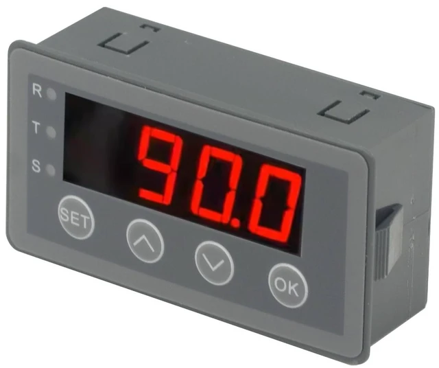
Digital Display Meter 0-10V 0-20mA 2-10V 4-20mA Analog Signal Input Panel Meter Standard/RS485/Relay (Standard Edition)
- Digital Display Meter 0-10V 0-20mA 2-10V 4-20mA Analog Signal Input Panel Meter Standard/RS485/Relay; The meter can be called a universal analog input display meter. It can be matched with various sensors with analog output to display the actual physical quantity. Such as temperature transmitter, frequency converter, motor speed, pressure, liquid level etc.; The instrument supports current input or voltage input.; Default adaptation: 0-10V, 2-10V, 0-20mA, 4-20mA. By setting the bias parameter and gain parameter, it can adapt to other inputs in the range of 0-10V, or 0-20mA.; It is displayed as a percentage by default. You can also set your own display range through F0-2 ~ F0-4.; Standard version and version with RS485, rated power supply voltage range: DC6~25V, power consumption: 24V/40mA;with relay output version, rated power supply voltage Range: DC8~25V, power consumption: 24V/50mA;power supply anti-reverse connection and surge protection
+
+
Overview
Specs
Reviews
Any questions? Ask CelesteSM will help you find out quickly.
Try me now
Product description Digital Display Meter 0-10V 0-20mA 2-10V 4-20mA Analog Signal Input Panel Meter Standard/RS485/Relay For the user manual file, please refer to the section below the introduction. For the user manual file, please refer to the section below the introduction. For the user manual file, please refer to the section below the introduction.
1.
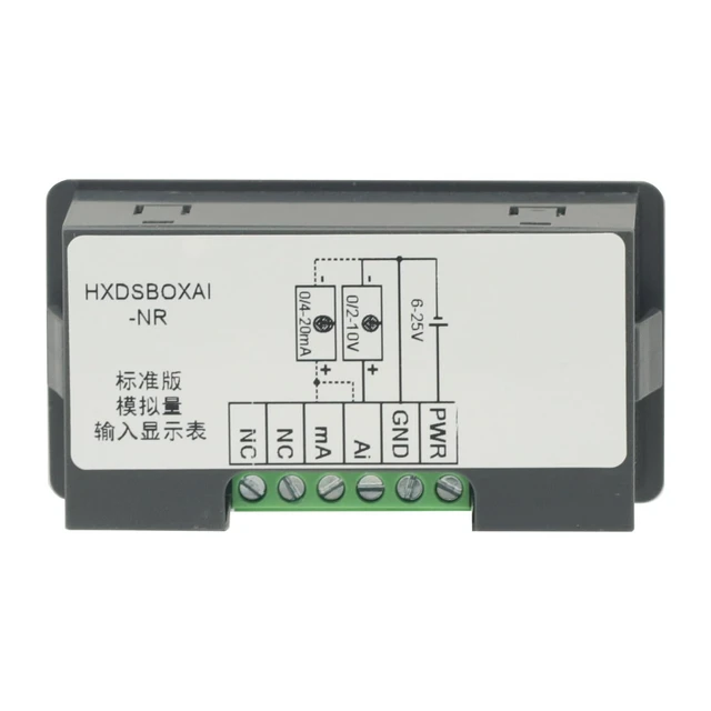
Model Description: Standard
Version: HXDSBOXAI-NR;
RS485 Version: HXDSBOXAI-485;
Relay Output Version: HXDSBOXAI-RL;
2. Standard Version and
RS485 Version: Rated
power supply voltage range: DC 625V, power
consumption: 24V/40mA;
Relay Output Version: Rated
power supply voltage range: DC 825V, power
consumption: 24V/50mA; Features reverse polarity protection and surge protection. 3. 1 analog input channel, selectable between voltage-type or current-type;
4.
Voltage-type input impedance: >30k
; current-type input impedance: <250;
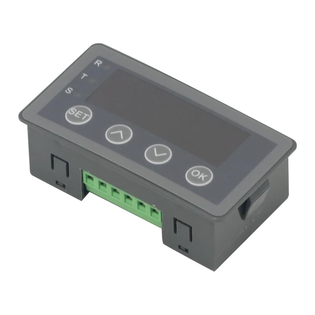
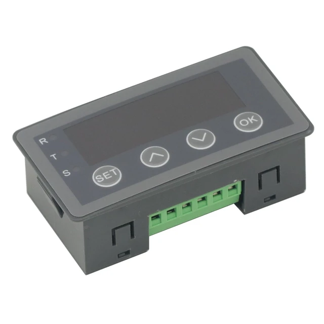
5. Rich parameter settings (please refer to the parameter specifications), built-in buttons for easy parameter configuration; 0.56 -inch 4-digit LED display; 6. RS485 version uses the standard Modbus-RTU protocol for easy networking; also supports inter-meter networking;
7. Relay output version with 1 normally open relay output; relay load capacity: 3A 30VDC/3A 250V AC;
8.
Mechanical dimensions: 79×43×25mm
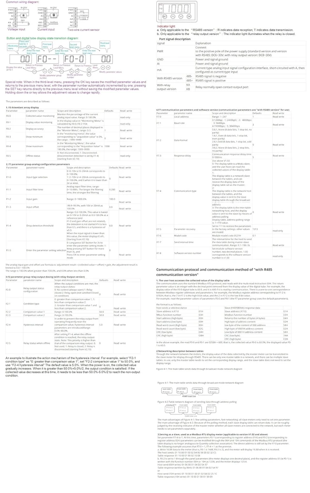
; mounting hole dimensions: 76.5 × 39.5 mm. Parameter description The parameters are described as follows: The analog input gain and offset use formula is: adjustment result = (collected value + offset) × gain, the adjustment result is limited to 0.0100. 0% The range is 100.0 % when greater than 100.0 %, and 0.0 % when less than 0.0 % F7-5 Parameter recovery Set to 111 to restore the parameters to the factory settings: other values are invalid. 1313 read-only F7-6 Model code Module model code 0521H 0.1 F7-7 Send interval time The interval time for the host to send the data table during master-slave communication.
Range: 0.1 ~100. 0s Read write F7-8 Software version number Set module software version number, two decimal places. 1.00 corresponds to the software version number is v 1.00 read-only
1. The user host accesses the collected value of the display table The communication uses the standard Modbus-RTU protocol, and reads with the multi-read instruction 03H. The return parameter value is an integer with the decimal point removed from the display value of the digital tube. For example, the display value of the F0-0 digital tube is 60.0, and it is 600 if it is read by communication. There is a one-to-one correspondence between Modbus register addresses and parameters. For example, the Modbus register address corresponding to F7-2 is 0702H, that is, the 7 in F7-2 is the high 8-bit value, and the 2 in F7-2 is the low 8-bit value. For example, read the parameter values of parameters F0-0 and F0-1 (the F7 parameter group uses the default parameters), the
format is as follows: The main advantages of
Figure 4-1: few setting parameters, fast networking; all slave meters only need to set one parameter. The main advantage of
Figure 4-2: Because of the polling method, each slave display table can return data. It can be roughly judged by the receiving indicator of the master meter whether all slave meters are connected to the network, but each meter needs to set parameters separately. 3. Serving as a slave, used as a Modbus-RTU display meter (applicable to version V 1.02 and above) Set parameter F7-4 to
1. At this time, parameters F0-1 (corresponding to register address 01H) and F0-2 (corresponding to register address 02H) parameters can be modified through the 06H and 10H commands of the Modbus-RTU protocol (the table display is no longer analogous to Quantity collection association). The device address is still set by the F7-0 parameter. The following example assumes that F7-0 = 1, F7-4 = 1 as the premise. a. Write 16.88 data to the meter (that is, F0-1 is 1688, F0-2 is 2), and the meter will display 16.88 when it is received.
The host sends: 01 10 00 01 00 02 0
1.
Model Description: Standard
Version: HXDSBOXAI-NR;
RS485 Version: HXDSBOXAI-485;
Relay Output Version: HXDSBOXAI-RL;
2. Standard Version and
RS485 Version: Rated
power supply voltage range: DC 625V, power
consumption: 24V/40mA;
Relay Output Version: Rated
power supply voltage range: DC 825V, power
consumption: 24V/50mA; Features reverse polarity protection and surge protection. 3. 1 analog input channel, selectable between voltage-type or current-type;
4.
Voltage-type input impedance: >30k
; current-type input impedance: <250;
5. Rich parameter settings (please refer to the parameter specifications), built-in buttons for easy parameter configuration; 0.56 -inch 4-digit LED display; 6. RS485 version uses the standard Modbus-RTU protocol for easy networking; also supports inter-meter networking;
7. Relay output version with 1 normally open relay output; relay load capacity: 3A 30VDC/3A 250V AC;
8.
Mechanical dimensions: 79×43×25mm
; mounting hole dimensions: 76.5 × 39.5 mm. Parameter description The parameters are described as follows: The analog input gain and offset use formula is: adjustment result = (collected value + offset) × gain, the adjustment result is limited to 0.0100. 0% The range is 100.0 % when greater than 100.0 %, and 0.0 % when less than 0.0 % F7-5 Parameter recovery Set to 111 to restore the parameters to the factory settings: other values are invalid. 1313 read-only F7-6 Model code Module model code 0521H 0.1 F7-7 Send interval time The interval time for the host to send the data table during master-slave communication.
Range: 0.1 ~100. 0s Read write F7-8 Software version number Set module software version number, two decimal places. 1.00 corresponds to the software version number is v 1.00 read-only
1. The user host accesses the collected value of the display table The communication uses the standard Modbus-RTU protocol, and reads with the multi-read instruction 03H. The return parameter value is an integer with the decimal point removed from the display value of the digital tube. For example, the display value of the F0-0 digital tube is 60.0, and it is 600 if it is read by communication. There is a one-to-one correspondence between Modbus register addresses and parameters. For example, the Modbus register address corresponding to F7-2 is 0702H, that is, the 7 in F7-2 is the high 8-bit value, and the 2 in F7-2 is the low 8-bit value. For example, read the parameter values of parameters F0-0 and F0-1 (the F7 parameter group uses the default parameters), the
format is as follows: The main advantages of
Figure 4-1: few setting parameters, fast networking; all slave meters only need to set one parameter. The main advantage of
Figure 4-2: Because of the polling method, each slave display table can return data. It can be roughly judged by the receiving indicator of the master meter whether all slave meters are connected to the network, but each meter needs to set parameters separately. 3. Serving as a slave, used as a Modbus-RTU display meter (applicable to version V 1.02 and above) Set parameter F7-4 to
1. At this time, parameters F0-1 (corresponding to register address 01H) and F0-2 (corresponding to register address 02H) parameters can be modified through the 06H and 10H commands of the Modbus-RTU protocol (the table display is no longer analogous to Quantity collection association). The device address is still set by the F7-0 parameter. The following example assumes that F7-0 = 1, F7-4 = 1 as the premise. a. Write 16.88 data to the meter (that is, F0-1 is 1688, F0-2 is 2), and the meter will display 16.88 when it is received.
The host sends: 01 10 00 01 00 02 0
Warranty & Returns
Warranty, Returns, And Additional Information
Warranty
- Please contact the Seller directly for warranty information. Warranty information may also be found on the Manufacturer's website.
- CONTACT
Return Policies
- Return for refund within: 30 days
- Return for replacement within: 30 days
- This item is covered by EmpressTech Return Policy
Manufacturer Contact Info
- For a directory of all our manufacturers, please click below.
- Manufacturers Directory
LOADING...