Your Browsing History
Meet Your Seller
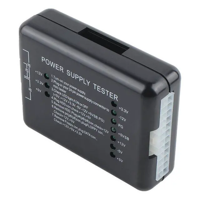
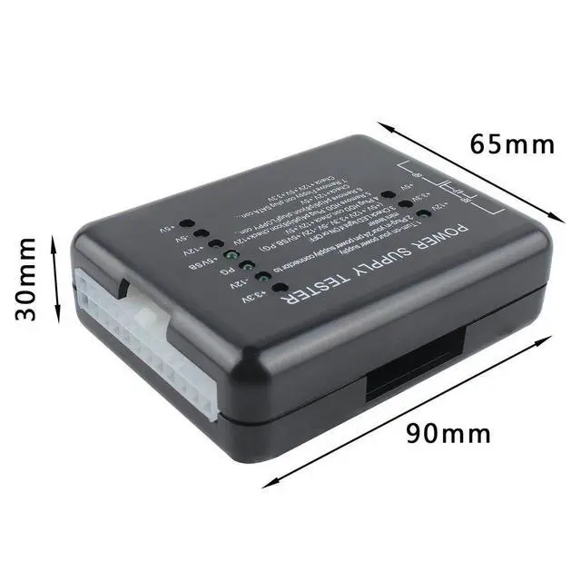
PC Power Supply Tester ATX Power Supply Diagnostic Tool, Computer PSU Tester, Digital LCD Display for Voltage Testing, PC Power Checker for Desktop Power Supplies
- Operating Instructions
- Connect the power supply to be tested to an AC power source.
- Plug the 24-pin (or 20-pin) connector of the power supply under test into the corresponding 24-pin (or 20-pin) socket on the tester.
- Check whether the seven indicators on the right side (+3.3V, -12V, PG, +5VSB, +12V, -5V, +5V) are lit. All seven should be illuminated for a good reading.
- Plug a HDD connector from the power supply under test into the HDD socket on the tester, then check whether the two indicators on the left side (+12V, +5V) are lit. Both should be illuminated.
- Remove the HDD connector from the tester, then plug a P4 (or P6/P8) connector into the corresponding P4 (or P6/P8) socket on the tester. Check whether the single indicator on the left side (+12V) is lit. It should be illuminated.
- Remove the P4 (or P6/P8) connector from the tester, then plug a FLOPPY connector into the corresponding FLOPPY socket on the tester. Check whether the two indicators on the left side (+12V, +5V) are lit. Both should be illuminated.
- Remove the FLOPPY connector from the tester, then plug a SATA connector into the corresponding SATA socket on the tester. Check whether the three indicators on the left side (+12V, +3.3V, +5V) are lit. All three should be illuminated.
+
+
Overview
Specs
Reviews
Any questions? Our AI beta will help you find out quickly.
Try me now
Product Introduction
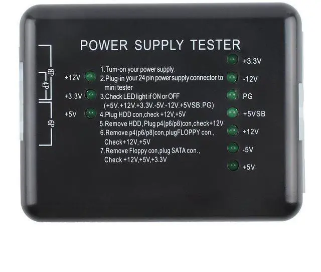
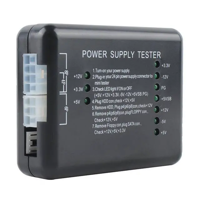
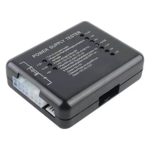
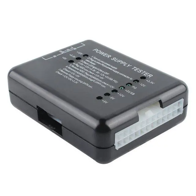
The Power Supply Tester is a powerful power supply diagnostic device that can test ATX, BTX, and ITX computer power supplies. It displays individual voltage levels and the PG (Power Good) value, making it an essential tool for quickly diagnosing PC power supplies.
Operating Instructions
- Connect the power supply to be tested to an AC power source.
- Plug the 24-pin (or 20-pin) connector of the power supply under test into the corresponding 24-pin (or 20-pin) socket on the tester.
- Check whether the seven indicators on the right side (+3.3V, -12V, PG, +5VSB, +12V, -5V, +5V) are lit. All seven should be illuminated for a good reading.
- Plug a HDD connector from the power supply under test into the HDD socket on the tester, then check whether the two indicators on the left side (+12V, +5V) are lit. Both should be illuminated.
- Remove the HDD connector from the tester, then plug a P4 (or P6/P8) connector into the corresponding P4 (or P6/P8) socket on the tester. Check whether the single indicator on the left side (+12V) is lit. It should be illuminated.
- Remove the P4 (or P6/P8) connector from the tester, then plug a FLOPPY connector into the corresponding FLOPPY socket on the tester. Check whether the two indicators on the left side (+12V, +5V) are lit. Both should be illuminated.
- Remove the FLOPPY connector from the tester, then plug a SATA connector into the corresponding SATA socket on the tester. Check whether the three indicators on the left side (+12V, +3.3V, +5V) are lit. All three should be illuminated.
Specifications
- Input Connector: 20/24-pin (ATX connector)
- Voltage Monitoring: +12V, -12V, +5V, -5V, +3.3V, +5V Standby (SB), +12V, and Power Good (PG)
- Connector Ports: Floppy, HDD, CDROM, SATA, 4-pin (P4), 8-pin (Dual-CPU), 6-pin (PCI-Express)

Warranty & Returns
Warranty, Returns, And Additional Information
Warranty
- Please contact the Seller directly for warranty information. Warranty information may also be found on the Manufacturer's website.
- CONTACT
Return Policies
- Return for refund within: 30 days
- Return for replacement within: 30 days
- This item is covered by SlotNeat Return Policy
Manufacturer Contact Info
- For a directory of all our manufacturers, please click below.
- Manufacturers Directory
LOADING...