Origin:Mainland China
Type:Air Conditioner Parts
modname=ckeditor
VT-3010KJ electro-hydraulic proportional amplifying board is an upgraded version of VT-3010SD electro-hydraulic proportional amplifying board. Two electromagnets are synchronously controlled by an input signal, so as to achieve the purpose of synchronous operation of two electro-hydraulic proportional variable pumps.
input 0-10V
Output 0-800MA
VT-3010KJ electro-hydraulic proportional amplifying board is an upgraded version of VT-3010SD electro-hydraulic proportional amplifying board. Two electromagnets are synchronously controlled by an input signal, so as to achieve the purpose of synchronous operation of two electro-hydraulic proportional variable pumps.
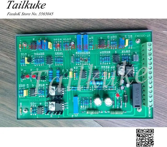
Wiring instructions, check the wiring numbers on the circuit board
1. The power supply of the controller is DC 24V, the positive end of the power supply is connected to 20, and the negative end is connected to 16 or 18;
2. Connect 28 and 24 at both ends of electromagnet A. Electromagnet B is connected to 26 and 22 at both ends. And no directionality;
3. The input controller signal (+9V) is taken out from 10, and the 0-+9V control signal is input from 12 through the external potentiometer, and the square wave modulation current of 0-800MA is synchronously obtained in electromagnets A and B.
Two potentiometers P3 and P4 are used to adjust the rise and fall time of the ramp. If ramp time is not required, please short 2 and 4.
The maximum output current value can be arbitrarily controlled by adjusting P5. The output current is 800MA when the control voltage reaches +9V when the product leaves the factory. If the system does not need such a large current, please adjust P5 to meet the needs.
P1 and P2 are used to adjust the leading current in electromagnets A and B, respectively. When the product leaves the factory, the first current in the two electromagnets is 0. Under normal circumstances, users do not need to adjust these two potentiometers.
When the electro-hydraulic proportional valve amplifier board is energized, the light-emitting diode L3 is on, when the electromagnet A has current, L1 is on, and when the electromagnet B has current, L2 is on. The user can judge the working condition of the amplifier board through the working condition of the three light-emitting diodes.