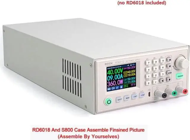
pizarra Assembly step
Note:The case material is a bit and may be slightly deformed during transportation. If there is a space during the assembly, straighten it it.
Back board assembly: install the rocker switchandAC power socketon the lower board.
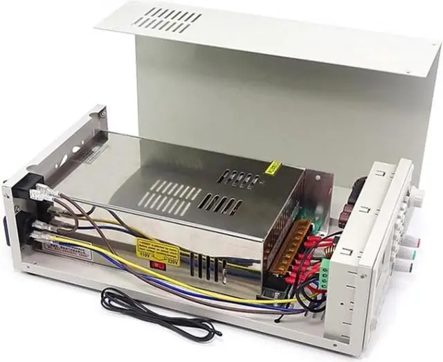
cables to switch power supply: (dangerous,non- should not operate)
Uselongbrown cable to therockerswitch and the live wire (L) of the switch power supply; then useshortbrown cable to therockerswitch and the live wire (L) of the AC power socket; Use the blue cable to the neutral wire (N) ofAC power socket and the neutral wire (N) of switch power supply; Use a yellow-green two-colorcableto the ground wire (E) ofAC power socket and the ground wire () of switch power supply.Use two red cables to the IN+ of the green terminal and the electrodes (+V), and use two black cables to the (IN-) of the terminals and negative electrodes (). Install the temperature sensor board to the back panel.
the switch power supply:Installthe switch power supply on the lower board
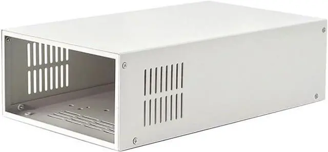
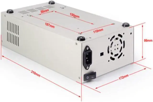
colour: creamy-white
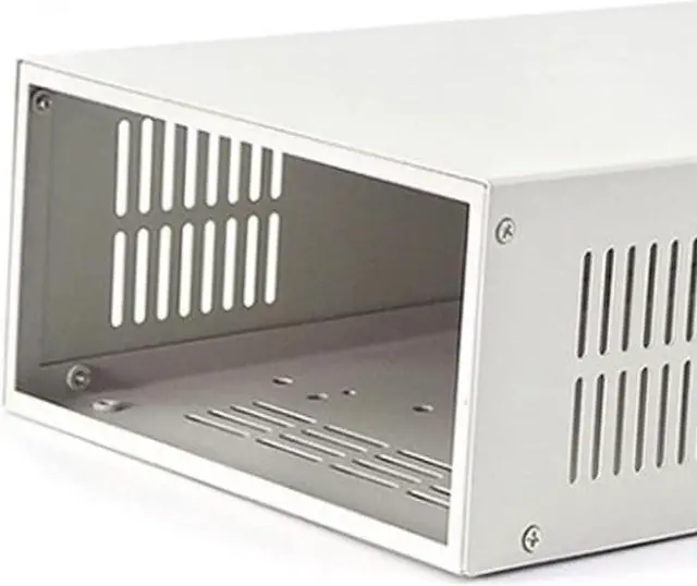
material: metal
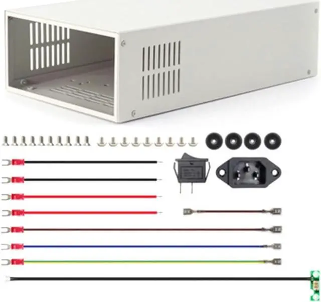
Contents:
1 x Top cover
1 x lower cover
9 x the wire
1 x switch
1 x Product socket
4 x Anti- mats
11 x Switching power supply/pad fixing screw
10 x Fixed screw for shell/product socket
Only the above content, other are not included.
Note: Light and different displays may the color of the item in the a little different from the real . The measurement allowed is +/- 1-3cm.
 M.2 2280 1TB PCIe 4.0 x4 with NVMe 1.4 TLC Internal Solid State Drive (SSD) TM8FFH001T0C128")
 TM8FFE004T0C129")