Your Browsing History
- Free 30-day Returns
$55.99

Meet Your Seller
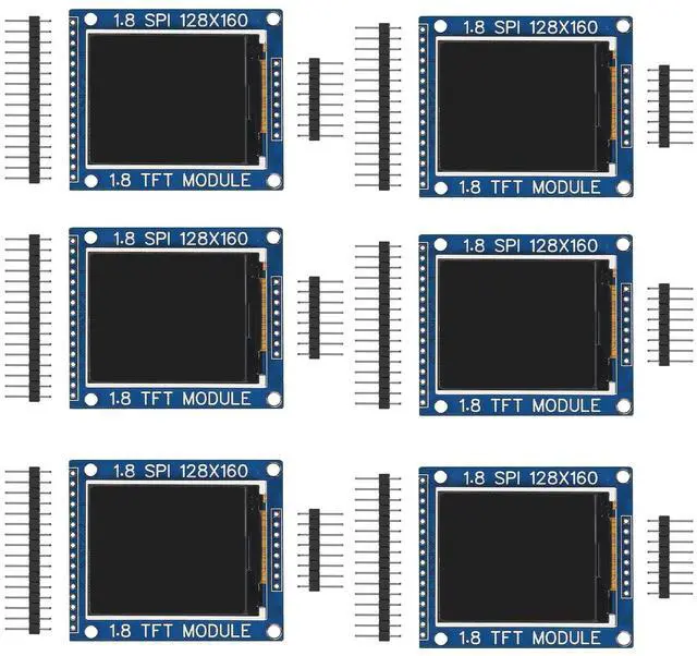
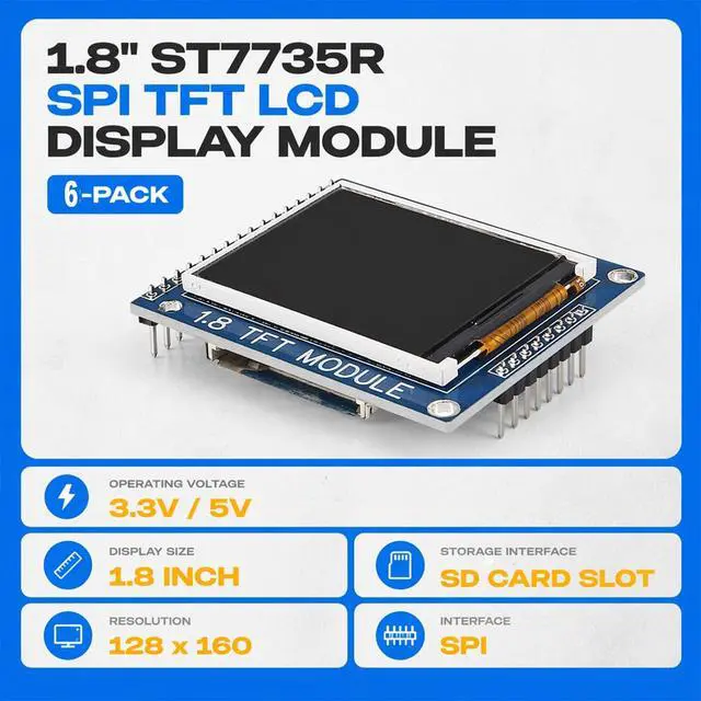
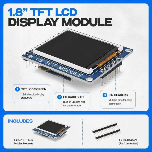
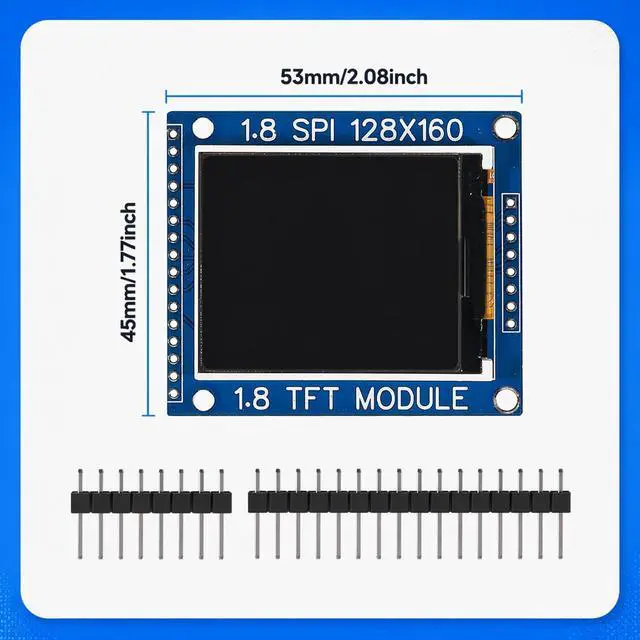
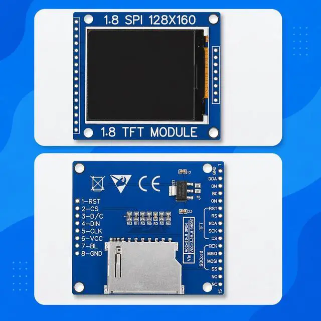


hiBCTR 6-Pack 1.8" ST7735R SPI TFT LCD Color Display Module (128x160) with SD Card Slot, Compatible with ESP32, STM32, and DIY Microcontrollers
- [IMPORTANT: POWER CONFIGURATION] By default, the onboard jumper (J1) on the back is OPEN, requiring a 5V power supply for VCC and Backlight (BL). To operate the board strictly on 3.3V, you MUST solder the J1 jumper closed. Please verify your voltage before powering on.
- [STRICT PINOUT VERIFICATION] Do not rely on universal wiring diagrams; pin directions (Pins 1-16) on this module may be reversed compared to other ST7735 screens. Always verify the silkscreen labels on the back of your specific PCB before connecting to your microcontroller.
- [DUAL-ROW EXPANDABILITY] Row 1 comes with pre-installed headers for display functions. Row 2 consists of unpopulated pin holes that break out the Integrated SD Card Slot and additional TFT pins; soldering is required to enable SD storage.
- [3.3V LOGIC COMPATIBLE] Even when powered by 5V VCC, this module's logic interface is fully compatible with 3.3V systems like ESP32 and STM32, as well as 5V systems like Arduino Uno.
- Only online doc
+
+
Overview
Specs
Reviews
Any questions? Our AI beta will help you find out quickly.
Try me now
[IMPORTANT: POWER CONFIGURATION] By default, the onboard jumper (J1) on the back is OPEN, requiring a 5V power supply for VCC and Backlight (BL). To operate the board strictly on 3.3V, you MUST solder the J1 jumper closed. Please verify your voltage before powering on. ^^ [STRICT PINOUT VERIFICATION] Do not rely on universal wiring diagrams; pin directions (Pins 1-16) on this module may be reversed compared to other ST7735 screens. Always verify the silkscreen labels on the back of your specific PCB before connecting to your microcontroller. ^^ [DUAL-ROW EXPANDABILITY] Row 1 comes with pre-installed headers for display functions. Row 2 consists of unpopulated pin holes that break out the Integrated SD Card Slot and additional TFT pins; soldering is required to enable SD storage. ^^ [ 3.3V LOGIC COMPATIBLE] Even when powered by 5V VCC, this module's logic interface is fully compatible with 3.3V systems like ESP32 and STM32, as well as 5V systems like Arduino Uno. ^^ Only online documents availableTo support eco-friendly packaging, paper user manuals will no longer be provided. You can contact the seller's customer service to obtain the complete pin diagram, library files and technical manual.
Warranty & Returns
Warranty, Returns, And Additional Information
Warranty
- Please contact the Seller directly for warranty information. Warranty information may also be found on the Manufacturer's website.
- CONTACT
Return Policies
- Return for refund within: 30 days
- Return for replacement within: 30 days
- This item is covered by Qiangsheng kuajing (Hong Kong) Co., Limi Return Policy
Manufacturer Contact Info
- For a directory of all our manufacturers, please click below.
- Manufacturers Directory
LOADING...