




 here!
here!
I’m your shopping assistant for PC builds, upgrades, and everything tech.
Got questions? Ask away!
Start a conversation
here!
I’m your shopping assistant for PC builds, upgrades, and everything tech.
Got questions? Ask away!
Start a conversation



Any questions? Ask CelesteSM will help you find out quickly.
 Description:
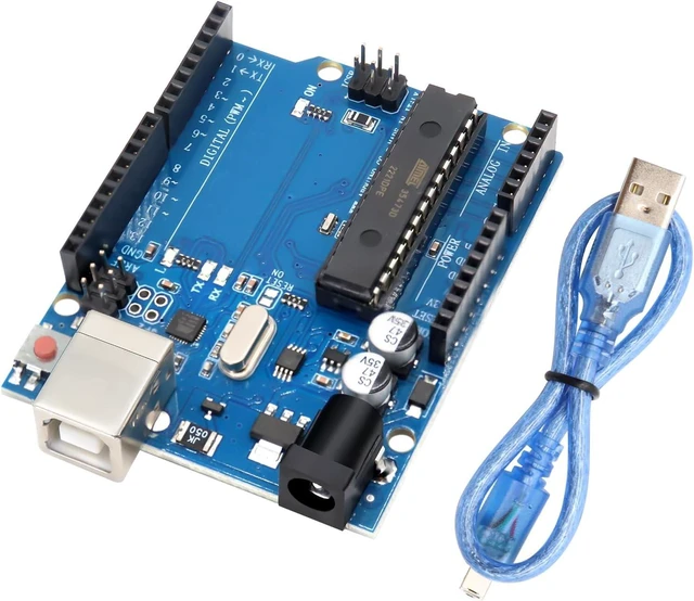
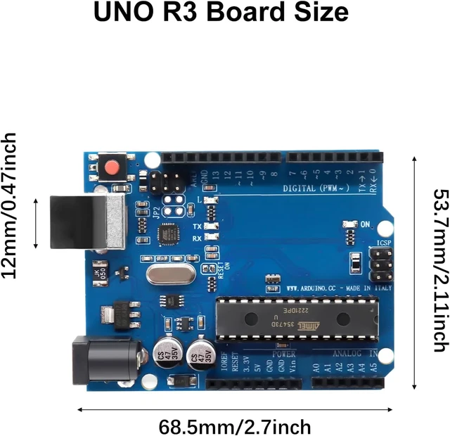
The R3 development board is a powerful microcontroller development platform based on the ATmega328P chip with 2 KB and 1 KB EEPROM, which is perfectly compatible with the Ar-duino-U-N-O.
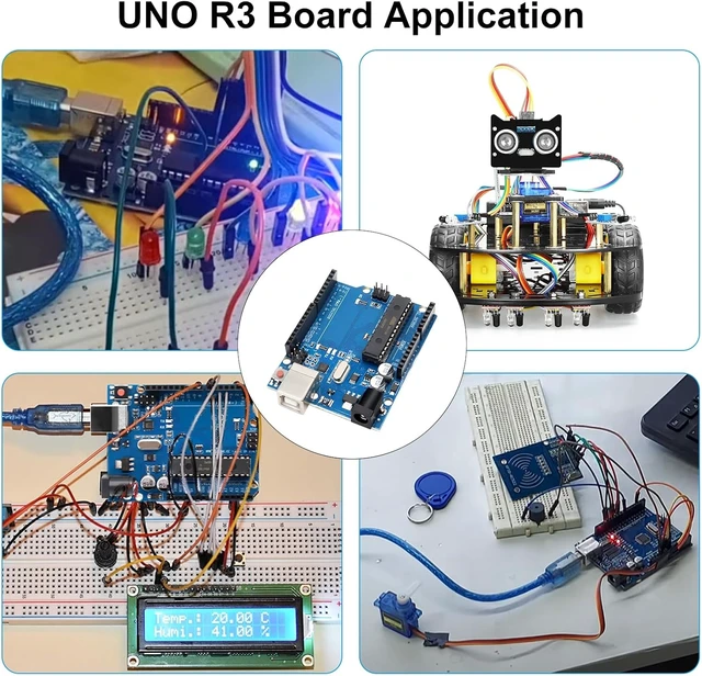
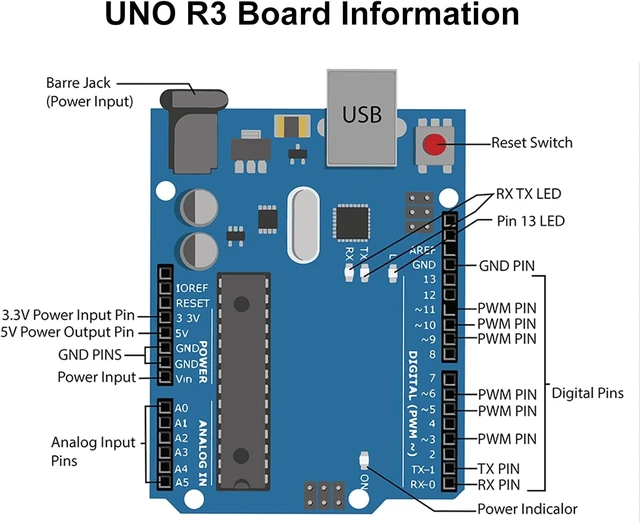
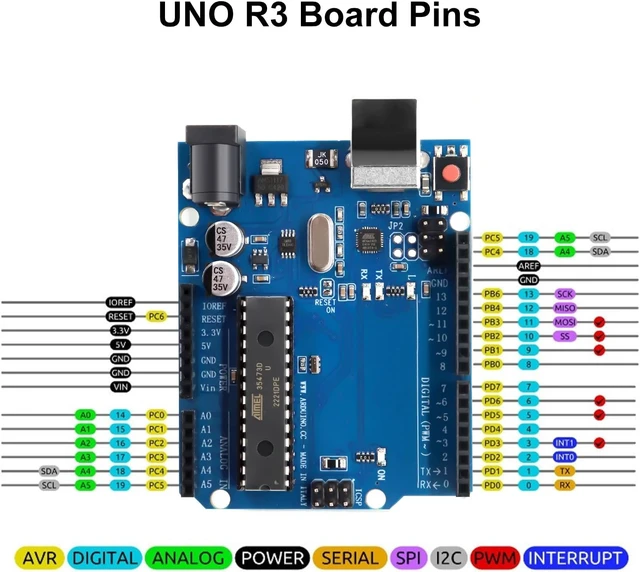
It provides a rich input and output interface, including 14 digital pins and 6 analog input pins, suitable for a variety of embedded development and control applications.
The R3 development board is equipped with a USB port, which supports programming and power supply through a USB connection, facilitating rapid debugging and development.
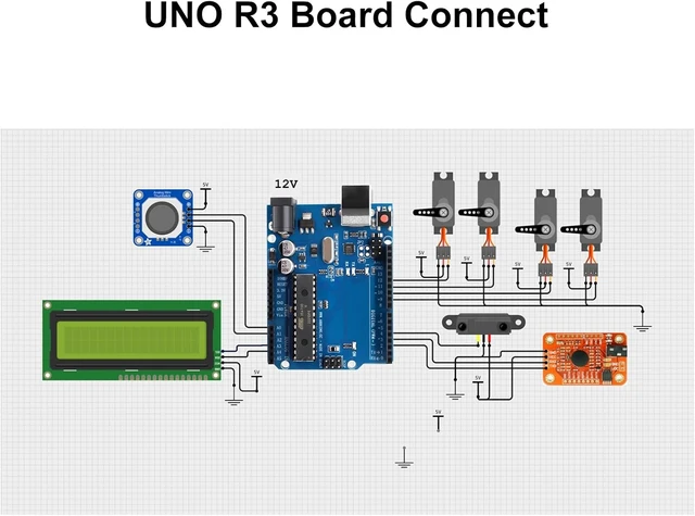
Fully compatible with the Ar-duino IDE, you can directly use a wealth of open source libraries and sample codes to quickly implement hardware control, sensor acquisition, and other project functions.
 Function:
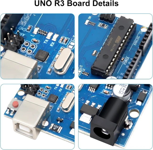
1.Pin change: Two I2C pins are added next to the AREF pin (SDA and SCL are just copies of Analog 4 and 5, with no additional I2C interfaces). In addition, two pins are added next to RESET. One is IOREF, which allows the expansion board to adapt to the onboard voltage. This pin only tells the expansion board what the current onboard voltage is (for example, is 5V, which can be seen as a copy of the power pin and does not provide level pull-up). The other is a placeholder pin for future use.
2.Stable RESET circuit: The RESET button's position has changed and moved to the corner of the board near the USB interface, which is more convenient for installation.
3.ATmega16U2: Enable R3 to simulate USB HID, such as MIDI/Joystick/Keyboard.
Parameters:
Input voltage (recommended): 7-12V
Digital I/O pins: 14 (6 of which provide PWM output)

Analog input pins: 6
DC current on 3.3V pin: 50 mA

Flash memory: 32 KB
Clock speed: 16MHz


