




 here!
I’m your shopping assistant for PC builds, upgrades, and everything tech.
Got questions? Ask away!
Start a conversation
here!
I’m your shopping assistant for PC builds, upgrades, and everything tech.
Got questions? Ask away!
Start a conversation
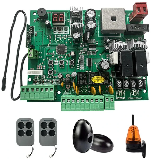
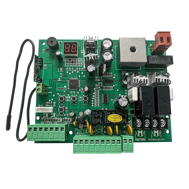



Any questions? Ask CelesteSM will help you find out quickly.
Features
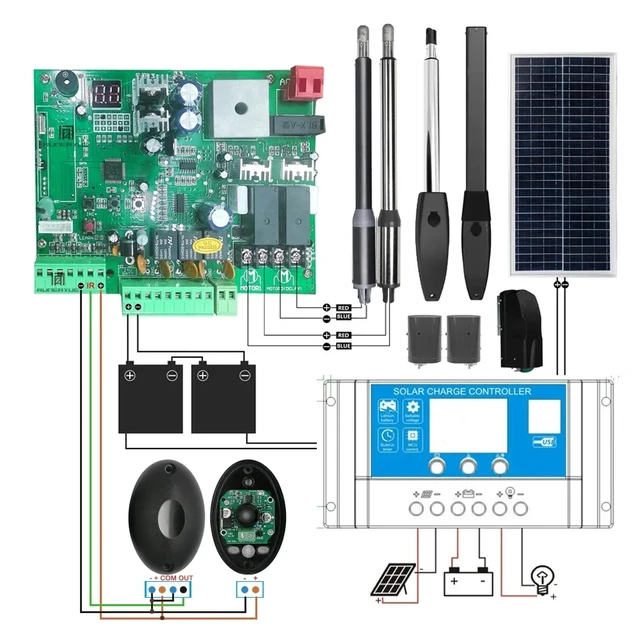
1.Control panel voltage input: 24VDCAC. Can connect 2PCS 12V 9AH back up battery.
Note that the control board purchased separately needs to be used with a transformer, and cannot be directly 100-250V AC.
2.Motor's voltage: 12-24VDC support.The input of the control board is 24V, and the output is 12-24V.
3.Encoder for transmitter: Use our own customized rolling code.(Encrypted code, no copying and non-branding of our products )
4.Range of application: Suit for our double arms swing gate openers.
*The Linear Spiral 24V Straight Brush Arm is supported, but only fully works with our products, and is not covered by the warranty if tested on a non-ours product.
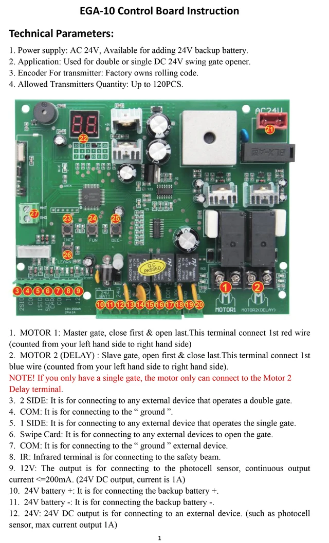
Technical Parameters:
1. Power supply: AC 24V, Available for adding 24V backup battery.
2. Application: Used for double or single DC 24V swing gate opener.
3. Encoder For transmitter: Factory owns rolling code.
4. Allowed Transmitters Quantity: Up to 120PCS.
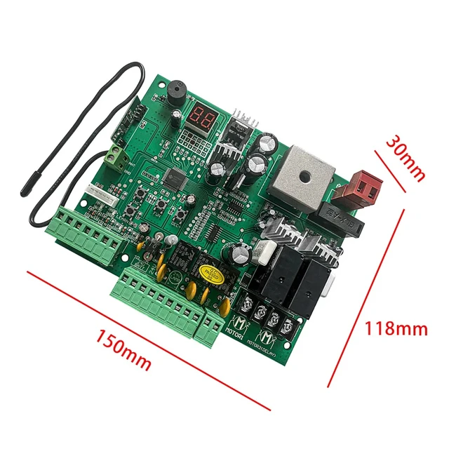
1. MOTOR 1: Master gate, close first & open last. This terminal connect 1st red wire
(counted from your left hand side to right hand side)
2. MOTOR 2 (DELAY) : Slave gate, open first & close last. This terminal connect 1st
blue wire (counted from your left hand side to right hand side).
Delay terminal
NOTE! If you only have a single gate, the motor only can connect to the Motor 2
3. 2 SIDE: It is for connecting to any external device that operates a double gate.
4. COM: It is for connecting to the " ground
5. 1 SIDE: It is for connecting to any external device that operates the single gate.
6. Swipe Card: It is for connecting to any external devices to open the gate.
7. COM: It is for connecting to the " ground " external device.
8. IR: Infrared terminal is for connecting to the safety beam.
9. 12V: The output is for connecting to the photocell sensor, continuous output
current <=200mA. (24V DC output, current is 1A)
10. 24V battery +: It is for connecting the backup battery +.
11. 24V battery -: It is for connecting the backup battery -.
12. 24V: 24V DC output is for connecting to an external device. (such as photocell
sensor, max current output 1A)
13. GND: It is for connecting to the " ground" of an external device.
14. 24V LAMP +: It is for connecting to the flash light +.
15. 24V LAMP -: It is for connecting to the flash light -.
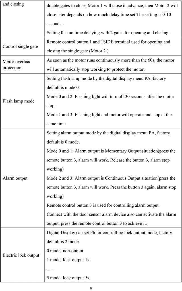
16. LOCK(NF): The NF terminal which used for connecting to the electric lock.
17. COM(24V): COMMON used for connecting to the"ground"of the lock.
18. LOCK(NA): The NA terminal which used for connecting to the magnetic lock.
19. GND: It is for connecting to the " ground " of the alarm system.
20. SP: It is 24V DC output connecting with the alarm system.
21. AC 24V: It is for connecting with the transformer.
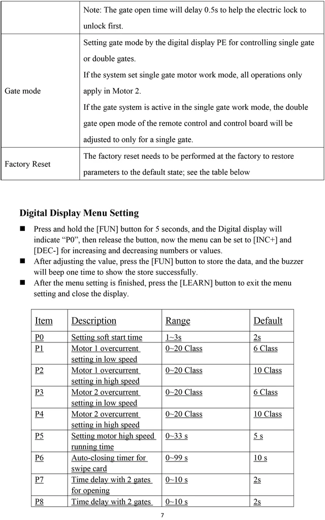
22. Digital display: It is for showing you the setting data.
23. INC+: It is for figure increasing of setting the data.
24. FUN: Used for enter the menu setting and confirm the data.
25. DEC-: It is for figure decreasing of setting the data.
26. Learning button: It is for programming/erasing the remote control.
27. ANT and GND: used to connect with antenna.
Program new remote control:
Press the LEARN button on the control board for about 1 second, and theindicator LED will turn off, then means entering the programming.Press any button on the new remote control for about 2 seconds. The digitaldisplay will show the remote's number while the board's indicator LED flashesfour times with buzzer sound, which means the programming is successful.Note! After you press the LEARN button, if the board does not receive the newremote signal within 5s, the indicator LED will turn on and exit programming.
Erase remote control:
Press and hold the LEARN button for about 5 seconds. If there has one buzzersound and indicator LED light on, then now means removing the remote
successfully.


