Nintendo Model:GameBoy Color
Model Number:EPSP360
is_customized:N
With USB:N
Item:GBC Backlight Mod Adaptor,Flex Cable
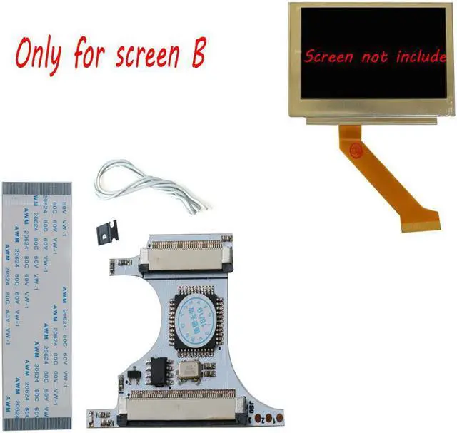
Works with:For GBASP AGS-101 Backlight LCD(White Ribbon cable Type)
modname=ckeditor
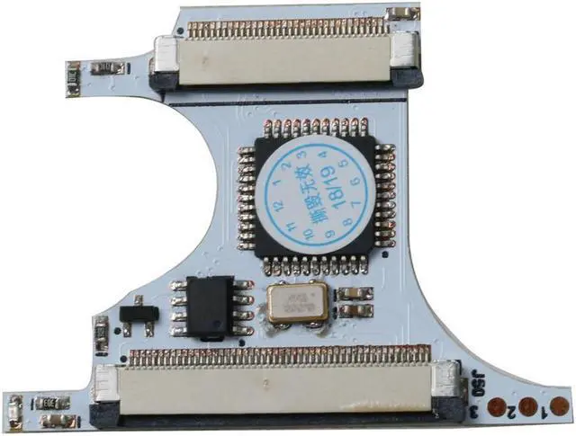
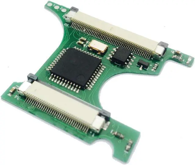
GBC Backlight Mod Adaptor Five-level brightness with memory GBC Flex Cable Game Console Repair Accessories
Caution:
This adaptor works with GBASP AGS-101 Backlight LCD(White Ribbon cable Type),None-Backlight GBC LCD cannot be used. CGB-CPU-B Type Mother Board is NOT recommended, image display would probably not stable.
Useful tools:
Knife,Diagonal pliers,File,Screwdriver,Electric soldering iron,Glue,Black tape.
GBC Backlight Mod Adaptor
Installation:
Step 1: GBC Housing shell trimming
Disassemble your GBC, taking out Mother broad and LCD, place the upper housing shell, all parts marked by red label need to be removed, using Knife and file or other tools which you could find to clear any plastic protruding within the red marked area.
Taking a close look of this step, all arrow pointing parts(including power indicated lamp positionScrew hole etc need to be removed). As the GBASP AGS-101 Backlight LCD is a little thicker than the None-Backlight LCD, thus you must polishing the thickness of this area into 1/2 comparing with shell,if your housing shell is crystal material,please be careful to do this.
Because of the size of the GBASP AGS-101 LCD, power switch cannot be right placed into the groove of the GBC housing shell. Thus, please follow the picture show to cut the upper part from the red line of the power switch. Turn upside down to make the switch fit for the power button of mother broad when place the trimmed switch into the GBC housing shell.
Tips:
Housing shell trimming work is the most critical step of GBC Backlight Mod, excellent work would make all steps easy and save your time, so please be patient to make every trimming work better.
Step 2: Mother Broad soldering and trimming
After housing shell trimming work, step 2 is Mother Broad soldering and trimming. See the picture shows, cut all soldered dots marked as red line(including cart slot soldered dotscommunication slot soldered dots and volume knob soldered dots),following by using electronic soldering iron to remove power indicate lamp.
Warning:
As the mother broad of the GBC including high-precision circuits and easy to be broken ,therefore it must be a very careful work of this step, if you do not have the Diagonal pliers,please use nail scissors instead.
Step 3: Final assemble and test
In order to reduce the thickness of the GBASP AGS-101 LCD, it is strongly suggested to remove to the front iron protect frame of the GBASP AGS-101 LCD,using Screwdriver to unclench buckles from the backside of LCD and then remove the front iron protect frame. The Picture shows is what the ront iron protect frame looks like. Be careful when doing this work as the LCD is Fragile
Final work:
When assemble all parts together, the LCD with iron protected back cover would likely leading mother broad short circuit, therefore, it is useful to paste a plastic tap on the backside of LCD.
After finishing all these work, it is testing time now. Power up your machine first, if all parts are install properly, the blue indicate lamp on the adaptor will light up, and image will display on the backlight LCD.
If you guys see the screen blink, please re-check the soldering work in step2.
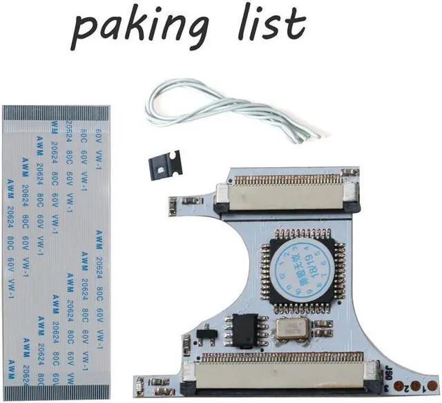
Packing Includes:
1*GBC Backlight Mod Adaptor
1*GBC Flex Cable
Note:1?The products are black, white, green, consistent in function, and the colors are randomly sent.
2?This product is only suitable for B-screen. The B-screen is as shown below. The lines on the yellow cable are equally thick. Please check carefully before purchasing.